

Question: ## NOTICE 1. I can't recognize your Cursive. 2. Please use MATHEMATICAL EDITOR if you can, so I can see the equations clearly. 3. Please
## NOTICE 1. I can't recognize your Cursive. 2. Please use MATHEMATICAL EDITOR if you can, so I can see the equations clearly. 3. Please explain IN DETAIL. I'm beginner. Thank you.
Q. When an adder is part of a larger digital system, an arrangement like the given figure often works well. For the control signals and the input data in the following table, give the value of the addend, the accumulator, and the bus at the end of each clock cycle (immediately before the active clock edge). Express the register and bus values in decimal.
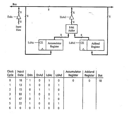
EnAd --A Enla Z Input Data LoAc CE Accumulator LdAd CE Register Register Clock Input Accumulator Addend Cycle Data Enin EnAd LdAC LdAd Register Register Bus 0 18 1 0 13 15 3 93 1 0 0 1 4 47 0 1 1 0
Step by Step Solution
There are 3 Steps involved in it

Get step-by-step solutions from verified subject matter experts