

Question: Objective: Design a water tank overflow detection system using sensors , logic gates, and sequential elements in Multisim. This system will: Monitor water levels (
Objective:
Design a water tank overflow detection system using sensors logic gates, and sequential elements in Multisim. This system will:
Monitor water levels low medium, high
Control a pump based on the water level.
Trigger an alarm when the tank reaches overflow.
Instructions:
Part : Water Tank Overflow System StepbyStep Guide in Multisim
Step : Setting Up Water Level Sensors Marks
Open Multisim:
Start Multisim and create a new blank circuit.
Add Digital Switches for Sensors:
From the Components Library, go to Place Component.
In the Component Browser, select Sources Digital Sources.
Choose Digital Switch often labeled as "Switch SPDT or similar and click to place it on the workspace.
Place four switches on the workspace to represent each water level:
Low L
Medium M
High H
Overflow O
Label the Switches:
Rightclick each switch, select Properties, and rename each switch according to the water level it represents
Configure Each Switch to Control Water Level:
These switches will represent whether a certain water level has been reached. When you toggle a switch, it simulates the tank reaching that specific level.
Initial State:
Keep all switches in the OFF position initially to show the tank is empty.
Screenshot: Capture a screenshot of this initial stqte with all switches OFF.
Step : Designing the Control Logic Marks
Obiective:
Step : Designing the Control Logic Marks
Objective:
The goal is to create logic circuits for controlling the pump and triggering an alarm based on the water levels. The pump should be ON when the water level is low, OFF when it reaches the high level, and the alarm should activate if there's an overflow.
Boolean Expressions:
Pump ON Condition:
Pump OFF Condition: High level detected H
Alarm Condition: Overflow level detected O
Place Logic Gates in Multisim:
Go to Place Component.
In the Component Browser, choose TTL or CMOS logic family to find gates.
Search for and place the following gates on the workspace:
AND gate for combining inputs.
NOT gate to create inverted signals and
OR gate if needed for combining additional logic.
Connect Switches to Logic Gates:
Connect the Low L switch directly to an AND gate.
Place NOT gates after the Medium M and High
H switches to produce and
Connect and to the AND gate to create the Pump ON Condition.
Connect the High H switch to another gate to represent the Pump OFF Condition.
Connect the Overflow O switch directly to an output eg LED or buzzer for the Alarm Condition.
Use Interactive Digital Probes:
Go to Instruments Probes Digital Probe.
Place a Digital Probe on each output of the logic circuit to monitor the pump and alarm states.
Verify the Outputs:
Test each water level condition by toggling the switches:
Low level only should turn ON the pump.
High level should turn OFF the pump.
Overflow level should activate the alarm.
Deliverables:
Screenshots: Capture screenshots of the circuit in each state Low Medium, High, Overflow and show the pump and alarm outputs.
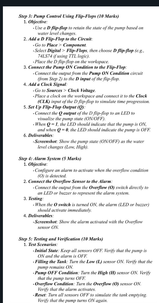
Step : Pump Control Using FlipFlops Marks
Objective:
Use a D flipflop to retain the state of the pump based on water level changes.
Add a D FlipFlop to the Circuit:
Go to Place Component.
Select Digital FlipFlops, then choose D flipflop eg if using TTL logic
Place the D flinflon on the workspace.
Step : Pump Control Using FlipFlops Marks
Objective:
Use a D flipflop to retain the state of the pump based on water level changes.
Add a D FlipFlop to the Circuit:
Go to Place Component.
Select Digital FlipFlops, then choose D flipflop egLS if using TTL logic
Place the D flipflop on the workspace.
Connect the Pump ON Condition to the FlipFlop:
Connect the output from the Pump ON Condition circuit from Step to the D input of the flipflop.
Add a Clock Signal:
Go to Sources Clock Voltage.
Place a clock on the workspace and connect it to the Clock CLK input of the D flipflop to simulate time progression.
Set Up FlipFlop Output Q:
Connect the Q output of the D flipflop to an LED to visualize the pump state ONOFF
When the LED should indicate that the pump is and when the LED should indicate the pump is OFF.
Deliverables:
Screenshot: Show the pump state ONOFF as the water level changes Low High
Step : Alarm System Mar
Step by Step Solution
There are 3 Steps involved in it
1 Expert Approved Answer
Step: 1 Unlock

Question Has Been Solved by an Expert!
Get step-by-step solutions from verified subject matter experts
Step: 2 Unlock
Step: 3 Unlock