

Question: Objective To implement a linear feedback shift register (LFSR) using a behavioral style. To use user defined primitives to design a structural adder. To read
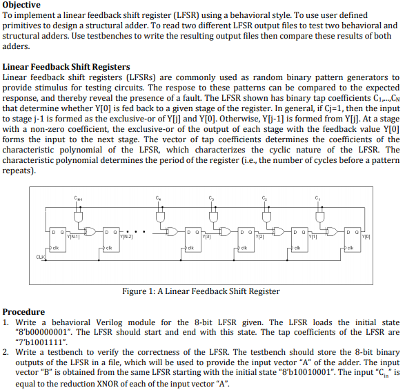
Objective To implement a linear feedback shift register (LFSR) using a behavioral style. To use user defined primitives to design a structural adder. To read two different LFSR output files to test two behavioral and structural adders. Use testbenches to write the resulting output files then compare these results of both adders. Linear Feedback Shift Registers Linear feedback shift registers (LFSRs) are commonly used as random binary pattern generators to provide stimulus for testing circuits. The respose to these patterns can be compared to the expected response, and thereby reveal the presence of a fault. The LFSR shown has binary tap coefficients C1 CN that determine whether Y[O] is fed back to a given stage of the register. In general, if Cj-1, then the input to stage j-1 is formed as the exclusive-or of Ylj] and Y[0]. Otherwise, Yj-1] is formed from Yj]. At a stage with a non-zero coefficient, the exclusive-or of the output of each stage with the feedback value Y[0] forms the input to the next stage. The vector of tap coefficients determines the coefficients of the characteristic polynomial of the LFSR, which characterizes the cyclic nature of the LFSR. The characteristic polynomial determines the period of the register i.e., the number of cycles before a pattern repeats). clk ck clk ck ck Figure 1: A Linear Feedback Shift Register Procedure 1. Write a behavioral Verilog module for the 8-bit LFSR given. The LFSR loads the initial state "8'b00000001". The LFSR should start and end with this state. The tap coefficients of the LFSR are 7'b1001111" 2. Write a testbench to verify the correctness of the LFSR. The testbench should store the 8-bit binary outputs of the LFSR in a file, which will be used to provide the input vector "A" of the adder. The input vector "B" is obtained from the same LFSR starting with the initial state "8'b10010001". The input "is equal to the reduction XNOR of each of the input vector "A" Objective To implement a linear feedback shift register (LFSR) using a behavioral style. To use user defined primitives to design a structural adder. To read two different LFSR output files to test two behavioral and structural adders. Use testbenches to write the resulting output files then compare these results of both adders. Linear Feedback Shift Registers Linear feedback shift registers (LFSRs) are commonly used as random binary pattern generators to provide stimulus for testing circuits. The respose to these patterns can be compared to the expected response, and thereby reveal the presence of a fault. The LFSR shown has binary tap coefficients C1 CN that determine whether Y[O] is fed back to a given stage of the register. In general, if Cj-1, then the input to stage j-1 is formed as the exclusive-or of Ylj] and Y[0]. Otherwise, Yj-1] is formed from Yj]. At a stage with a non-zero coefficient, the exclusive-or of the output of each stage with the feedback value Y[0] forms the input to the next stage. The vector of tap coefficients determines the coefficients of the characteristic polynomial of the LFSR, which characterizes the cyclic nature of the LFSR. The characteristic polynomial determines the period of the register i.e., the number of cycles before a pattern repeats). clk ck clk ck ck Figure 1: A Linear Feedback Shift Register Procedure 1. Write a behavioral Verilog module for the 8-bit LFSR given. The LFSR loads the initial state "8'b00000001". The LFSR should start and end with this state. The tap coefficients of the LFSR are 7'b1001111" 2. Write a testbench to verify the correctness of the LFSR. The testbench should store the 8-bit binary outputs of the LFSR in a file, which will be used to provide the input vector "A" of the adder. The input vector "B" is obtained from the same LFSR starting with the initial state "8'b10010001". The input "is equal to the reduction XNOR of each of the input vector "A
Step by Step Solution
There are 3 Steps involved in it

Get step-by-step solutions from verified subject matter experts