

Question: Objective You are to implement a circuit that will multiply a 3x4 matrix with its transpose. That is, the circuit will compute B where B
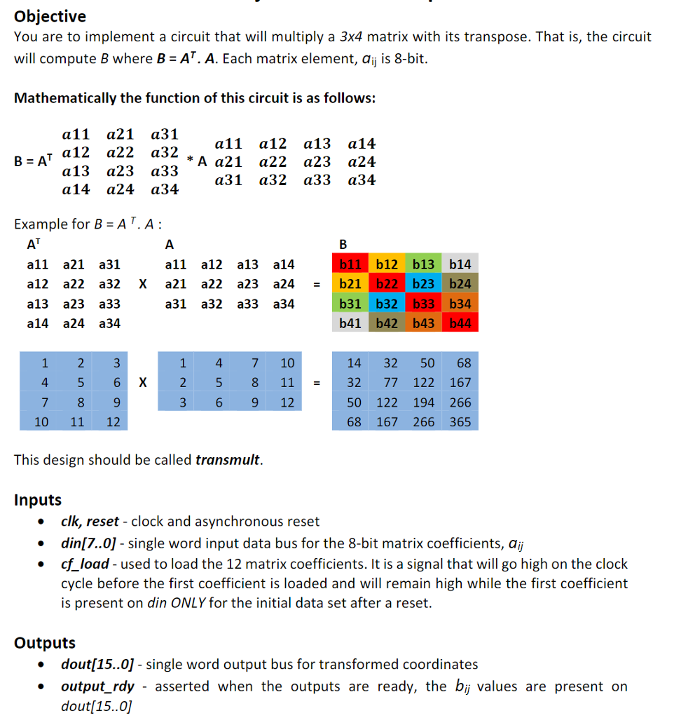
Objective You are to implement a circuit that will multiply a 3x4 matrix with its transpose. That is, the circuit will compute B where B AT. A. Each matrix element, aij is 8-bit. Mathematically the function of this circuit is as follows: a11 a21 a31 T a12 a22 a32 a13 a23 a33 a14 a24 a34 11 12 13 14 * 21 22 23 24 a31 a32 a33 a34 Example for B-AT.A b11 b12 b13 b14 all a21 a31 a12 a22 a32 X a21 a22 a23 a24 b21 b22b23 b24 a13 a23 a33 a14 a24 a34 all a12 a13 a14 b31 b32 b33 b34 b41 b42 b43 b44 a31 a32 a33 a34 1 4 7 10 14 32 50 68 2 5 8 1132 77 122 167 50 122 194 266 68 167 266 365 4 5 6X 3 6 9 12 10 11 12 This design should be called transmult Inputs * clk, reset - clock and asynchronous reset e din[7..0] - single word input data bus for the 8-bit matrix coefficients, ai * cf load - used to load the 12 matrix coefficients. It is a signal that will go high on the clock cycle before the first coefficient is loaded and will remain high while the first coefficient is present on din ONLY for the initial data set after a reset Outputs dout[15.0] - single word output bus for transformed coordinates output_rdy - asserted when the outputs are ready, the bij values are present on dout[15..0] * Objective You are to implement a circuit that will multiply a 3x4 matrix with its transpose. That is, the circuit will compute B where B AT. A. Each matrix element, aij is 8-bit. Mathematically the function of this circuit is as follows: a11 a21 a31 T a12 a22 a32 a13 a23 a33 a14 a24 a34 11 12 13 14 * 21 22 23 24 a31 a32 a33 a34 Example for B-AT.A b11 b12 b13 b14 all a21 a31 a12 a22 a32 X a21 a22 a23 a24 b21 b22b23 b24 a13 a23 a33 a14 a24 a34 all a12 a13 a14 b31 b32 b33 b34 b41 b42 b43 b44 a31 a32 a33 a34 1 4 7 10 14 32 50 68 2 5 8 1132 77 122 167 50 122 194 266 68 167 266 365 4 5 6X 3 6 9 12 10 11 12 This design should be called transmult Inputs * clk, reset - clock and asynchronous reset e din[7..0] - single word input data bus for the 8-bit matrix coefficients, ai * cf load - used to load the 12 matrix coefficients. It is a signal that will go high on the clock cycle before the first coefficient is loaded and will remain high while the first coefficient is present on din ONLY for the initial data set after a reset Outputs dout[15.0] - single word output bus for transformed coordinates output_rdy - asserted when the outputs are ready, the bij values are present on dout[15..0] *
Step by Step Solution
There are 3 Steps involved in it

Get step-by-step solutions from verified subject matter experts