

Question: OK , let's get started: The floor system shown below is from the second floor on a two - story steel - framed building. The
OK let's get started: The floor system shown below is from the second floor on a twostory
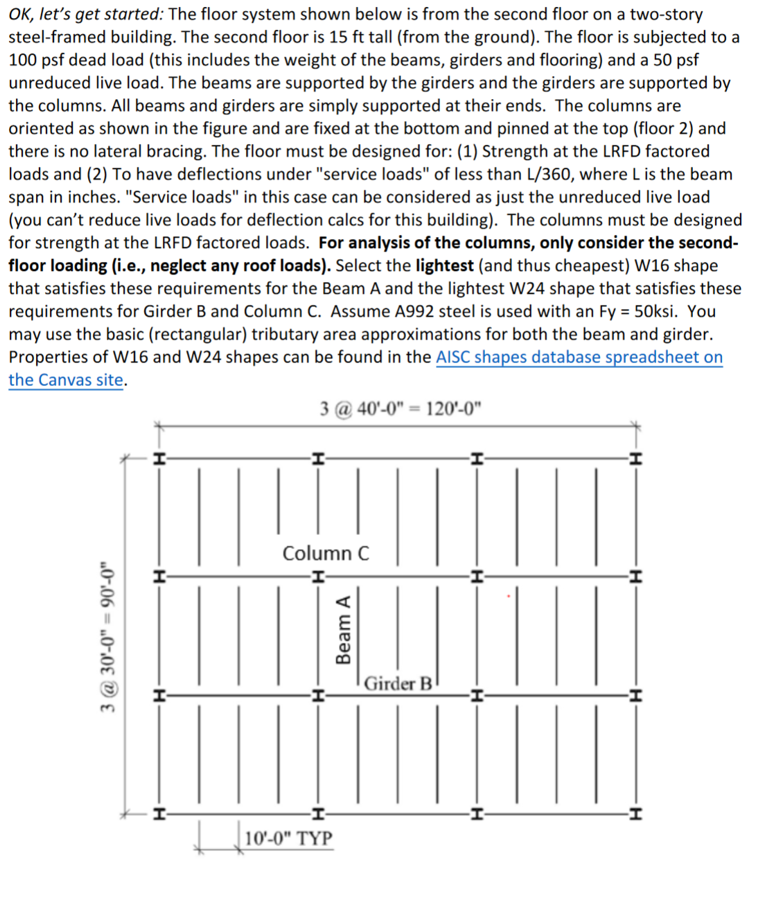
steelframed building. The second floor is tall from the ground The floor is subjected to a
psf dead load this includes the weight of the beams, girders and flooring and a psf
unreduced live load. The beams are supported by the girders and the girders are supported by
the columns. All beams and girders are simply supported at their ends. The columns are
oriented as shown in the figure and are fixed at the bottom and pinned at the top floor and
there is no lateral bracing. The floor must be designed for: Strength at the LRFD factored
loads and To have deflections under "service loads" of less than L where is the beam
span in inches. "Service loads" in this case can be considered as just the unreduced live load
you can't reduce live loads for deflection calcs for this building The columns must be designed
for strength at the LRFD factored loads. For analysis of the columns, only consider the second
floor loading ie neglect any roof loads Select the lightest and thus cheapest W shape
that satisfies these requirements for the Beam A and the lightest W shape that satisfies these
requirements for Girder B and Column C Assume A steel is used with an Fy ksi. You
may use the basic rectangular tributary area approximations for both the beam and girder.
Properties of W and W shapes can be found in the AISC shapes database spreadsheet on
the Canvas site.
Step by Step Solution
There are 3 Steps involved in it
1 Expert Approved Answer
Step: 1 Unlock

Question Has Been Solved by an Expert!
Get step-by-step solutions from verified subject matter experts
Step: 2 Unlock
Step: 3 Unlock