

Question: Only answer Problem 2 Note: I strongly recommend that you reference the ATmega128 datasheet when solving these questions. Problem #1 (25 pts] The AVR code
![ATmega128 datasheet when solving these questions. Problem #1 (25 pts] The AVR](https://dsd5zvtm8ll6.cloudfront.net/si.experts.images/questions/2024/09/66fa400dd2f1e_42966fa400d5a67f.jpg) Only answer Problem 2
Only answer Problem 2
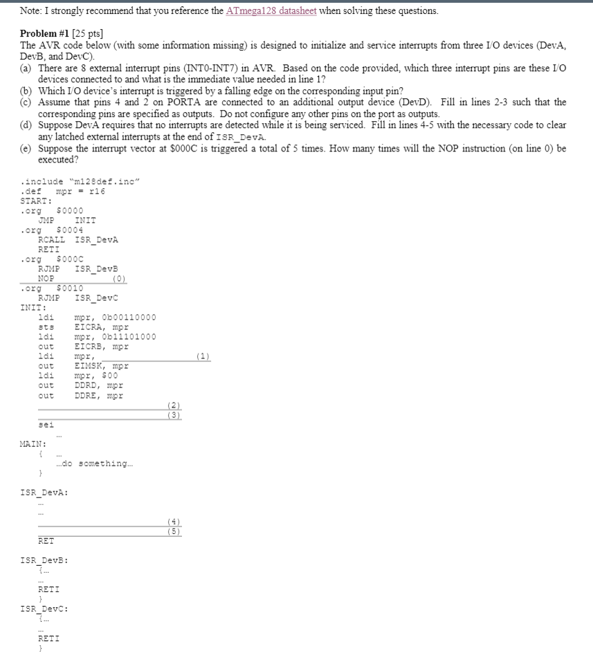
Note: I strongly recommend that you reference the ATmega128 datasheet when solving these questions. Problem #1 (25 pts] The AVR code below (with some information missing) is designed to initialize and service interrupts from three I/O devices (Deva, DevB, and DevC). (a) There are 8 external interrupt pins (INTO-INT7) in AVR. Based on the code provided, which three interrupt pins are these I/O devices connected to and what is the immediate value needed in line 1? (b) Which 10 device's interrupt is triggered by a falling edge on the corresponding input pin? C) Assume that pins 4 and 2 on PORTA are connected to an additional output device (DevD). Fill in lines 2-3 such that the corresponding pins are specified as outputs. Do not configure any other pins on the port as outputs. (d) Suppose DevA requires that no interrupts are detected while it is being serviced. Fill in lines 4-5 with the necessary code to clear any latched external interrupts at the end of ISR_DEVA. (e) Suppose the interrupt vector at $000C is triggered a total of 5 times. How many times will the NOP instruction on line 0) be executed? .include "2128 def.inc .de mpr = r16 START: .org $0000 JME INIT $0004 RCALL ISR_DEVA RETI .org $0000 RJMP ISR_DevB NOP (0) $0010 RJME ISR_Devc INIT: idi mor, Ob00110000 EICRA, mor idi mor, Ob11101000 out EICRB, mp idi mpr out EIMSK, mp ldi mpr, 900 out DDRD, mpe out DDRE, mor .029 (1) (2) sei MAIN: { ...do something.. ISR_DEVA: (5 RET ISR DevB: RETI ISR_Devc: RETI Problem #2 (25 pts] Consider the AVR code segment shown below (with some missing information) that configures Timer/Counter for Fast PWM operation, and modifies the Fast PWM duty cycle whenever a specific button on Port Dis pressed. (a) Fill in lines (1-2) with the instructions necessary to configure Timer/Counter for Fast PWM mode, non-inverting output, and a prescale value of 32. (6) Based on the prescale value used in part (a). what is the frequency of the PWM signal (own) being generated by Timer/Countero? Assume the system clock frequency is 16 MHz. (c) Fill in lines (3-4) to provide the compare value for Timer Counter so that the initial duty cycle is 0%. (d) What would be the value necessary for the variable step to increase the duty cycle by 18% each time the DUTY_STEP subroutine is executed? Ignore the case when if the compare value overflows. "m128 def.inc .include .der .def .equ mpr = r16 temp = r17 step = INIT: stack pointer is initialized ; ; set pin 4 (OCO) as output ; I/O ports idi mor, Ob00010000 out DDRB, mor idi mor, Ob00000000 out DDRD, mpr idi mor, Ob00000001 out PORTD, mor ; set pin o as input ; enable pull-up resistor for pin o ; Timer/Countero ; Fast FWM mode, non-inverting, prescale = 32 (1) (2) ; Initial compare value for PWM output (3) MAIN: sbis PIND, 0 rcall DUTY_STEP rymp MAIN DUTY STEP: push push mpr temp in idi add out mpe, temp, step mor, temp ; read the current PWM compare value ; add step value to compare value ; write new PWM compare value mor pop pop ret temp mor ; return Note: I strongly recommend that you reference the ATmega128 datasheet when solving these questions. Problem #1 (25 pts] The AVR code below (with some information missing) is designed to initialize and service interrupts from three I/O devices (Deva, DevB, and DevC). (a) There are 8 external interrupt pins (INTO-INT7) in AVR. Based on the code provided, which three interrupt pins are these I/O devices connected to and what is the immediate value needed in line 1? (b) Which 10 device's interrupt is triggered by a falling edge on the corresponding input pin? C) Assume that pins 4 and 2 on PORTA are connected to an additional output device (DevD). Fill in lines 2-3 such that the corresponding pins are specified as outputs. Do not configure any other pins on the port as outputs. (d) Suppose DevA requires that no interrupts are detected while it is being serviced. Fill in lines 4-5 with the necessary code to clear any latched external interrupts at the end of ISR_DEVA. (e) Suppose the interrupt vector at $000C is triggered a total of 5 times. How many times will the NOP instruction on line 0) be executed? .include "2128 def.inc .de mpr = r16 START: .org $0000 JME INIT $0004 RCALL ISR_DEVA RETI .org $0000 RJMP ISR_DevB NOP (0) $0010 RJME ISR_Devc INIT: idi mor, Ob00110000 EICRA, mor idi mor, Ob11101000 out EICRB, mp idi mpr out EIMSK, mp ldi mpr, 900 out DDRD, mpe out DDRE, mor .029 (1) (2) sei MAIN: { ...do something.. ISR_DEVA: (5 RET ISR DevB: RETI ISR_Devc: RETI Problem #2 (25 pts] Consider the AVR code segment shown below (with some missing information) that configures Timer/Counter for Fast PWM operation, and modifies the Fast PWM duty cycle whenever a specific button on Port Dis pressed. (a) Fill in lines (1-2) with the instructions necessary to configure Timer/Counter for Fast PWM mode, non-inverting output, and a prescale value of 32. (6) Based on the prescale value used in part (a). what is the frequency of the PWM signal (own) being generated by Timer/Countero? Assume the system clock frequency is 16 MHz. (c) Fill in lines (3-4) to provide the compare value for Timer Counter so that the initial duty cycle is 0%. (d) What would be the value necessary for the variable step to increase the duty cycle by 18% each time the DUTY_STEP subroutine is executed? Ignore the case when if the compare value overflows. "m128 def.inc .include .der .def .equ mpr = r16 temp = r17 step = INIT: stack pointer is initialized ; ; set pin 4 (OCO) as output ; I/O ports idi mor, Ob00010000 out DDRB, mor idi mor, Ob00000000 out DDRD, mpr idi mor, Ob00000001 out PORTD, mor ; set pin o as input ; enable pull-up resistor for pin o ; Timer/Countero ; Fast FWM mode, non-inverting, prescale = 32 (1) (2) ; Initial compare value for PWM output (3) MAIN: sbis PIND, 0 rcall DUTY_STEP rymp MAIN DUTY STEP: push push mpr temp in idi add out mpe, temp, step mor, temp ; read the current PWM compare value ; add step value to compare value ; write new PWM compare value mor pop pop ret temp mor ; return
Step by Step Solution
There are 3 Steps involved in it

Get step-by-step solutions from verified subject matter experts