

Question: only the fourth question CPS310 - COMPUTER ORGANIZATION II LAB 1 ALU, REGISTER DESIGN Submission instruction: students work in groups of 2, are expected to

only the fourth question
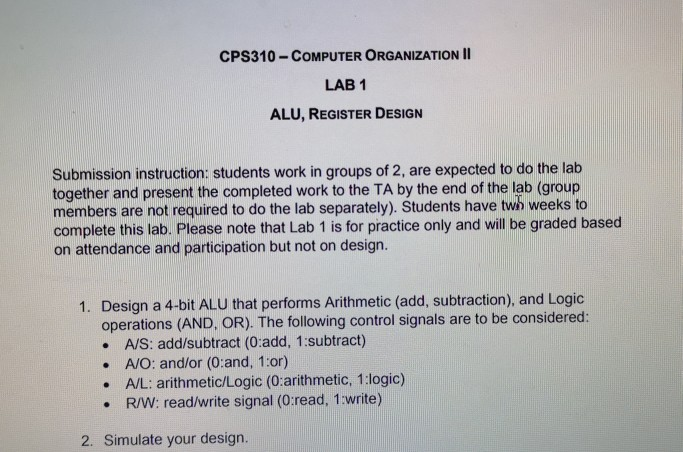
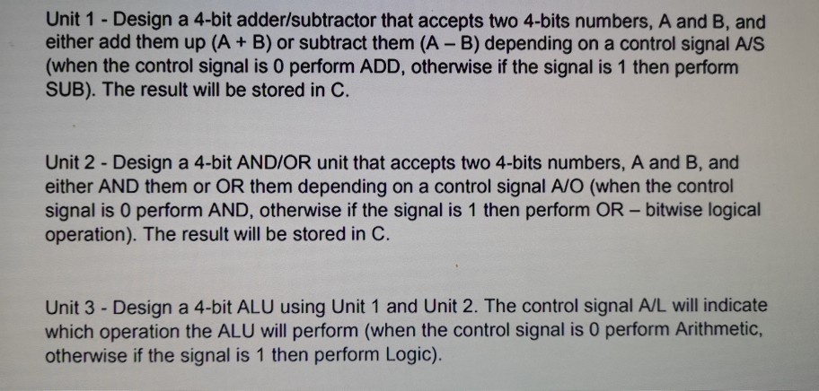
CPS310 - COMPUTER ORGANIZATION II LAB 1 ALU, REGISTER DESIGN Submission instruction: students work in groups of 2, are expected to do the lab together and present the completed work to the TA by the end of the lab (group members are not required to do the lab separately). Students have two weeks to complete this lab. Please note that Lab 1 is for practice only and will be graded based on attendance and participation but not on design. 1. Design a 4-bit ALU that performs Arithmetic (add, subtraction), and Logic operations (AND, OR). The following control signals are to be considered: A/S: add/subtract (0:add, 1:subtract) A/O: and/or (0:and, 1:or) A/L: arithmetic/Logic (0:arithmetic, 1:logic) R/W: read/write signal (0:read, 1:write) 2. Simulate your design. Unit 1 - Design a 4-bit adder/subtractor that accepts two 4-bits numbers, A and B, and either add them up (A + B) or subtract them (A - B) depending on a control signal A/S (when the control signal is O perform ADD, otherwise if the signal is 1 then perform SUB). The result will be stored in C. Unit 2 - Design a 4-bit AND/OR unit that accepts two 4-bits numbers, A and B, and either AND them or OR them depending on a control signal A/O (when the control signal is o perform AND, otherwise if the signal is 1 then perform OR - bitwise logical operation). The result will be stored in C. Unit 3 - Design a 4-bit ALU using Unit 1 and Unit 2. The control signal A/L will indicate which operation the ALU will perform (when the control signal is O perform Arithmetic, otherwise if the signal is 1 then perform Logic). Unit 4 - Design three 4-bit parallel registers to hold A, B, and C where C keeps the output of the ALU. The registers have a R/W control signal that indicates that they are being written to or read from
Step by Step Solution
There are 3 Steps involved in it

Get step-by-step solutions from verified subject matter experts