

Question: Option A: Problem statement Q: Develop a ladder logic program for the setup shown below: Sensors: 1 . Water level sensor which is a float
Option A: Problem statement
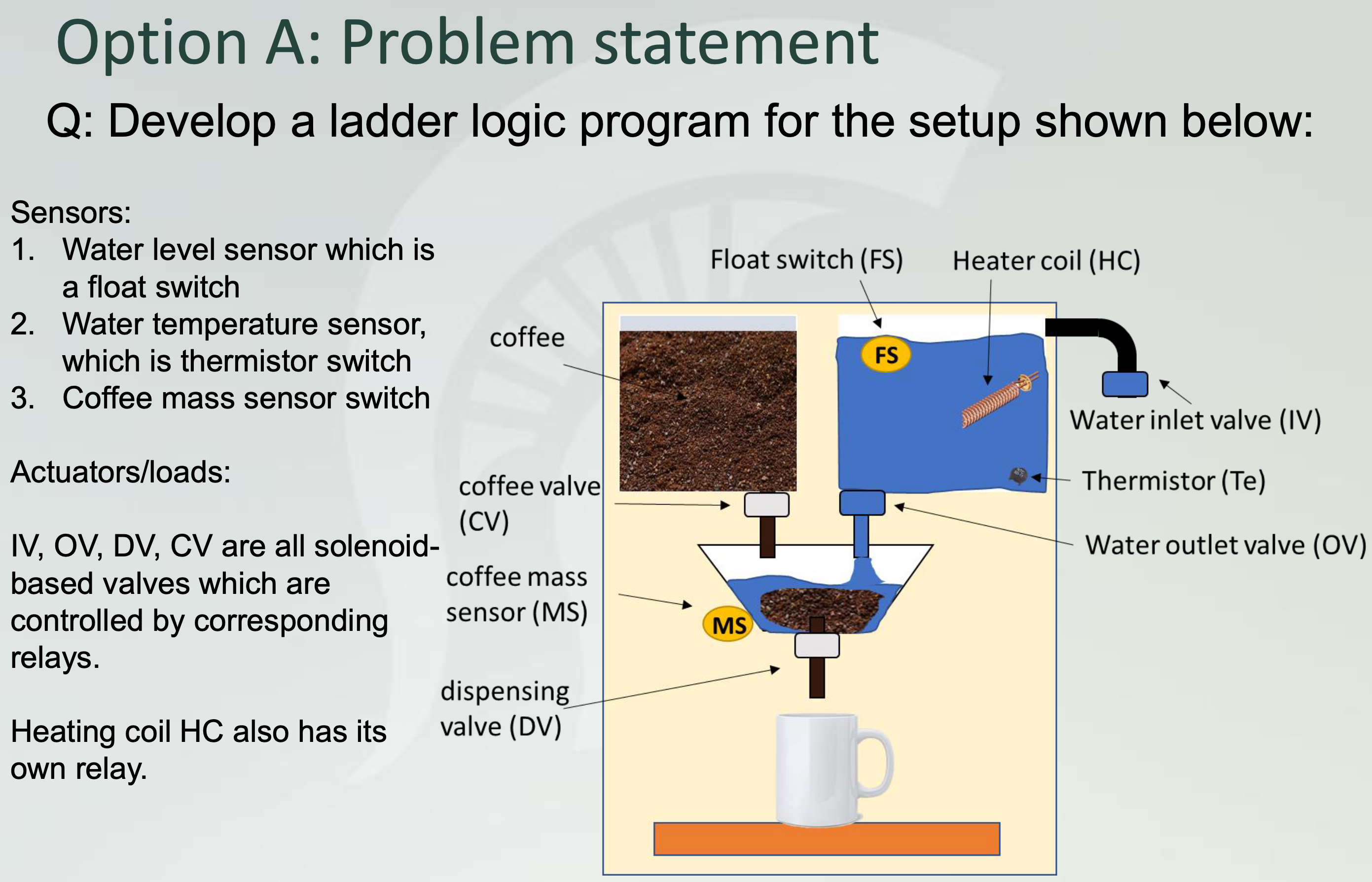
Q: Develop a ladder logic program for the setup shown below:
Sensors:
Water level sensor which is a float switch
Water temperature sensor which is thermistor switch
Coffee mass sensor switch
Actuatorsloads:
IV OV DV CV are all solenoidbased valves which are controlled by corresponding relays.
Heating coil HC also has its own relay. Flow chart for Option A
Start timer
T
The first steps are similar to HW where the water is filled automatically till preset level.
This is accomplished by opening the inlet valve IV till the water reaches the desired level, which is measured by float sensor FS
Next, the water is heated to a boil using the heater coil HC and measured by thermistor Te
Next, the ground coffee is dispensed using the coffee valve CV till present mass is attained. This is measured by the coffee mass sensor MS
Next, we pour hot water into the strainer using Outlet valve OV and a timer T For preset time, OV remains open.
Next, we soak the coffee using timer T
Finally, we open and dispense the coffee using a dispense valve DV and a timer T
Since we use sensor switches, we have an open and closed state, and each state has its corresponding logic. Requirements Option A
You are only required to submit the ladder logic.
Use the notations for example HC CV etc.. and sensors given here. Do not make any modifications to the sensors
You have to use binary logic, therefore, you cannot use any comparators.
To be fair to the entire class, you cannot use software for implementation or testing. This must be purely your contribution and the logic must be simple binary.
A key or legend of the sensors and actuators must be placed next to the ladder logic.
Ladder diagram must have rungs horizontal lines and rails vertical lines You MUST use the template given in class. See lecture video. This includes symbols for switches, coilsrelays and loads. Failure to use this template means you will be given points.
Rubric:
If you have an open logic, you will automatically get deduction. Open logic means a relay or load that is always being energized.
If there is no logic, you will get between depending on effort.
Step by Step Solution
There are 3 Steps involved in it
1 Expert Approved Answer
Step: 1 Unlock

Question Has Been Solved by an Expert!
Get step-by-step solutions from verified subject matter experts
Step: 2 Unlock
Step: 3 Unlock