

Question: P 1 1 . 1 Consider the small system shown in Figure P 1 1 . 1 . Each of the lines is modeled as
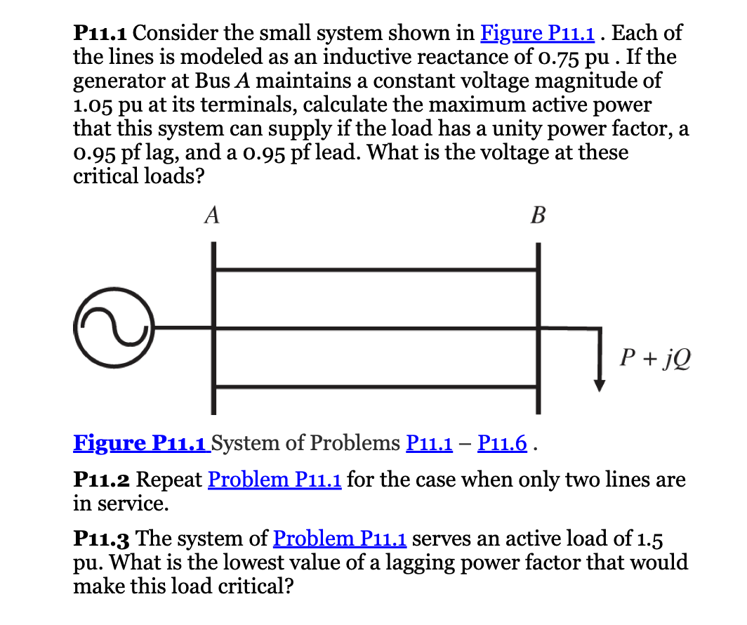
P Consider the small system shown in Figure P Each of the lines is modeled as an inductive reactance of pu If the generator at Bus A maintains a constant voltage magnitude of pu at its terminals, calculate the maximum active power that this system can supply if the load has a unity power factor, a pf lag, and a pf lead. What is the voltage at these critical loads?
n
Figure PSystem of Problems PP
P Repeat Problem P for the case when only two lines are in service.
P The system of Problem P serves an active load of pu What is the lowest value of a lagging power factor that would make this load critical?
Step by Step Solution
There are 3 Steps involved in it
1 Expert Approved Answer
Step: 1 Unlock

Question Has Been Solved by an Expert!
Get step-by-step solutions from verified subject matter experts
Step: 2 Unlock
Step: 3 Unlock