

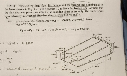
Question: P . 2 1 . 3 Calculate the shear flow distribution and the stringer and flange loads in the beam shown in Fig. P .
P Calculate the shear flow distribution and the stringer and flange loads in the beam shown in Fig. P at a section m from the builtin end. Assume that the skin and web panels are effective in resisting shear stress only; the beam tapers symmetrically in a vertical direction about its dongitudinal axis.
Ans.
Step by Step Solution
There are 3 Steps involved in it
1 Expert Approved Answer
Step: 1 Unlock

Question Has Been Solved by an Expert!
Get step-by-step solutions from verified subject matter experts
Step: 2 Unlock
Step: 3 Unlock