

Question: P1) The structure presented in the video Member with a hole - failure modes and design is reproduced here. You may use any values
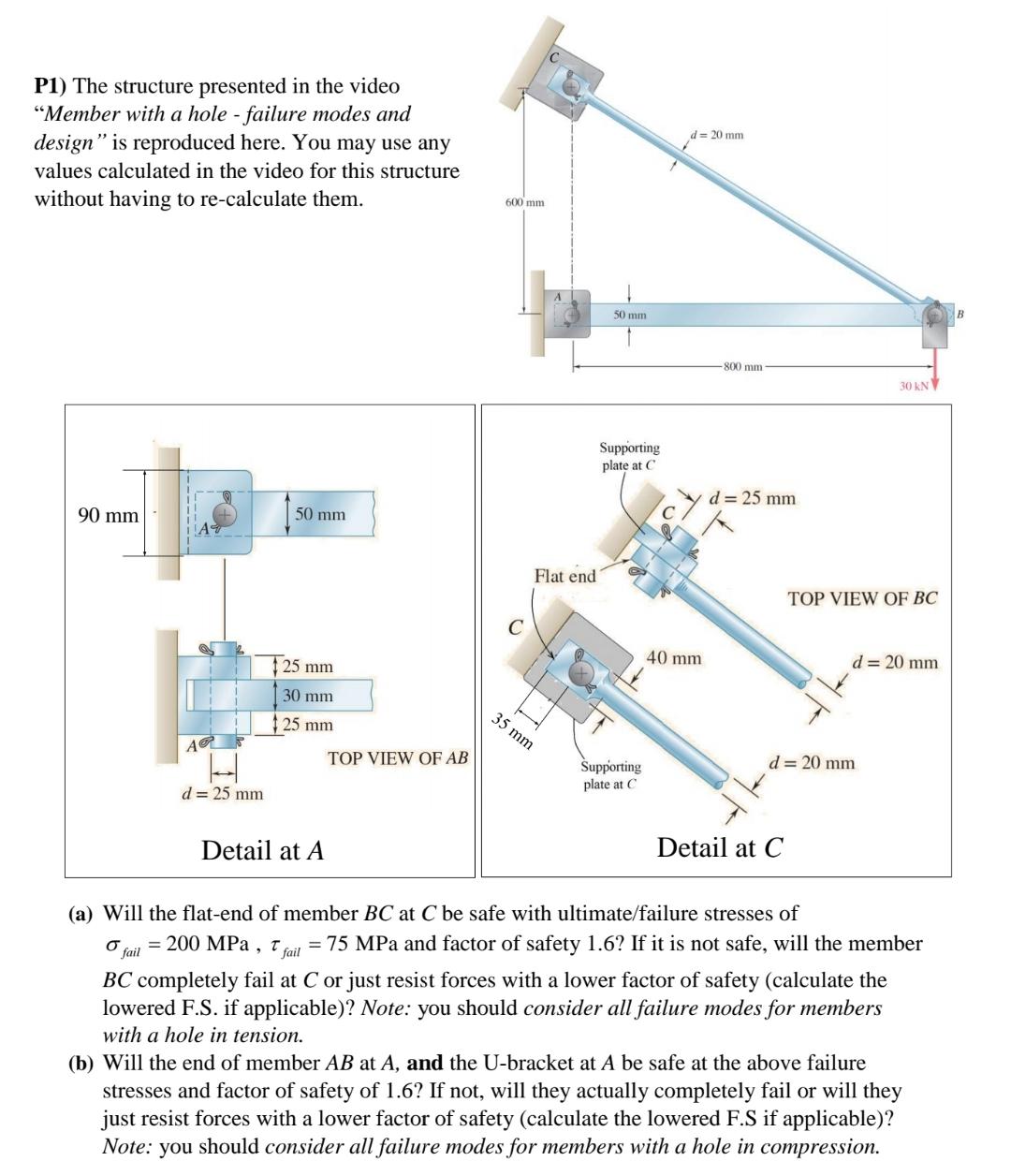
P1) The structure presented in the video "Member with a hole - failure modes and design" is reproduced here. You may use any values calculated in the video for this structure without having to re-calculate them. 90 mm d = 25 mm 50 mm 25 mm 30 mm 25 mm Detail at A TOP VIEW OF AB 600 mm. Flat end 35 mm 50 mm Supporting plate at C Supporting plate at C d = 20 mm 40 mm 800 mm d = 25 mm Detail at C 30 kN TOP VIEW OF BC d = 20 mm d = 20 mm (a) Will the flat-end of member BC at C be safe with ultimate/failure stresses of fail = 200 MPa, 7 fail = 75 MPa and factor of safety 1.6? If it is not safe, will the member BC completely fail at C or just resist forces with a lower factor of safety (calculate the lowered F.S. if applicable)? Note: you should consider all failure modes for members with a hole in tension. (b) Will the end of member AB at A, and the U-bracket at A be safe at the above failure stresses and factor of safety of 1.6? If not, will they actually completely fail or will they just resist forces with a lower factor of safety (calculate the lowered F.S if applicable)? Note: you should consider all failure modes for members with a hole in compression.
Step by Step Solution
There are 3 Steps involved in it
a To determine the safety of the flatend of member BC at C with ultimate and failure stresses of fail 200 MPa and fail 75 MPa respectively and a facto... View full answer

Get step-by-step solutions from verified subject matter experts