

Question: P2: This problem is adapted from Messac 2015 []. It involves a multiobjective formulation of a physically-meaningful structural optimization problem. It involves the use of
P2: This problem is adapted from Messac 2015 []. It involves a multiobjective formulation of a physically-meaningful structural optimization problem. It involves the use of formulas from solid mechanics, although background in this topic is not required for completing this problem. All relevant formulas are provided, and detailed supplementary notes for this engineering application are provided below. You will be asked to complete the formulation for this problem, including the model elements not provided directly, and solve this problem for its Pareto frontier using the epsilon constraint method. Consider the two-bar truss in the figure below:
We would like to design this truss such that it can support a downward vertical load of magnitude 2P without failing, while also considering the mass and deflection of the truss. The truss members are hollow cylinders connected by pin joints. The truss members are made of steel, which is an elastic material that deforms a small amount when a load is applied. For example, applying an axial load P to a single rod with a solid cross section produces the following deflection: = Pl EA where l is the length of the rod, A is the cross sectional area, and E is the modulus of elasticity, an intrinsic material property that corresponds to material stiffness. When we combine multiple rods together using joints to form a truss, the axial loads are distributed across truss members in a way that always depends on geometry, and sometimes also depends on material properties. In the simple truss shown in Fig. 5.1, it is possible to show that the downward deflection of node A due to a load 2P is: A = P(B2 +H2)32 DT EH2 The base width of the truss is B, the height is H, D is the rod diameter, and T is the wall thickness. The modulus of elasticity for steel is E = 10 106 psi. This is a fairly complex nonlinear dependence upon several quantities, including elements that might be chosen as design variables. There is going to be an obvious tradeoff between deflection and mass. To reduce deflection, we could make the rod cross sections thicker, but this will increase mass. This leads to identification of two conflicting objective functions that both need to be minimized: f1(x) = A f2(x) = m = V where m is the mass of both rods, = 0.3 lb/in3 is the density of steel, and V is the total material volume of the rods (which you will need to derive). Suppose the design variables are H and D (i.e., x = [H,D]T), whereas the following quantities are fixed parameters: B = 30 inches T = 0.10 inches
The value of H influences the axial load experienced by each rod. Referring back to the topic of resolving vector forces covered in a first course in physics, even with a fixed value for the load 2P, if we reduce H the axial load applied to each rod is amplified. Thus, small H requires large D to prevent failure and reduce deflection, but large H increases mass. We have mentioned failure, but how exactly might a structural truss like this fail? There are two main failure modes to consider: 1) axial stress from axial loads may cause yielding (you will need the component of force that is along the axial direction of each rod), as well as 2) elastic buckling. The axial stress can be modeled as the axial load divided by the cross-sectional area: = Fa A . You will need to derive what Fa is for each rod (note the symmetry). You may use the following approximation for the area of rod cross section: A = DT If the axial stress exceeds the yield strength of the material, this will cause plastic deformation of the material, and this is considered a failure. You can see this Wikipedia page for more details. The yield constraint can be expressed as: allow where the allowable stress allow can be assumed here to be a material yield strength value of Sy = 100 103 psi. The second important failure mode relates to elastic stability. Elastic buckling of a structural component occurs when enough compressive force is applied to cause the component to bow out sideways, and if the load is high enough it will result in elastic instability and collapse. You can see this Wikipedia page for some details about elastic buckling, as well as this video lecture from SE 410. You only need to consider linear buckling as modeled by Eulers buckling formula for the purposes of this homework problem. Preventing buckling using this model involves the constraint: Fa Pcr = 2EI L2 This expresses that the axial load on a rod in compression must not exceed a critical load for buckling (Pcr ), which depends upon geometry and material stiffness. The rod cross section area moment of inertia is I, and the length of the rod is L. Please note that different boundary conditions will result in a different multiplying factor for this formula. For a load of P = 33 103 lbs., variable bounds of: 0.5 D 5.0 inches 0.5 H 50 inches
please complete the following: a) Express the complete multiobjective problem formulation in standard negative-null form b) Derive all formulas needed for objective and constraint functions not already defined here c) Identify anchor points for this problem d) Use the epsilon-constraint method to generate 50 non-dominated points between these anchor points e) Plot and discuss the tradeoffs that you observe. It will help to look at the optimal design vectors for a sampling of points on the Pareto frontier.
![P2: This problem is adapted from Messac 2015 []. It involves a](https://dsd5zvtm8ll6.cloudfront.net/si.experts.images/questions/2024/11/6728f594c42fa_5566728f5943d1ce.jpg)
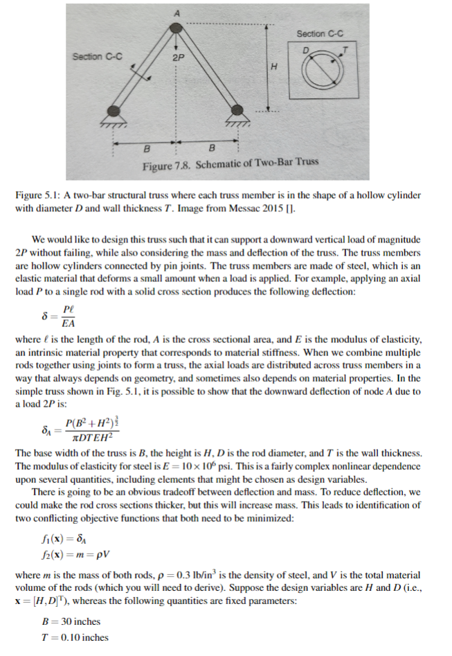
P2: This problem is adapted from Messac 2015 []. It involves a multiobjective formulation of a physically-meaningful structural optimization problem. It involves the use of formulas from solid mechanics, although background in this topic is not required for completing this problem. All relevant formulas are provided, and detailed supplementary notes for this engineering application are provided below. You will be asked to complete the formulation for this problem, including the model elements not provided directly, and solve this problem for its Pareto frontier using the epsilon constraint method. Consider the two-bar truss in the figure below: Figure 5.1: A two-bar structural truss where each truss member is in the shape of a hollow cylinder with diameter D and wall thickness T. Image from Messac 2015 []. We would like to design this truss such that it can support a downward vertical load of magnitude 2P without failing, while also considering the mass and deflection of the truss. The truss members are hollow cylinders connected by pin joints. The truss members are made of steel, which is an elastic material that deforms a small amount when a load is applied. For example, applying an axial load P to a single rod with a solid cross section produces the following deflection: =EAP where is the length of the rod, A is the cross sectional area, and E is the modulus of elasticity, an intrinsic material property that corresponds to material stiffness. When we combine multiple rods together using joints to form a truss, the axial loads are distributed across truss members in a way that always depends on geometry, and sometimes also depends on material properties. In the simple truss shown in Fig. 5.1, it is possible to show that the downward deflection of node A due to a load 2P is: A=DTEH2P(B2+H2)23 The base width of the truss is B, the height is H,D is the rod diameter, and T is the wall thickness. The modulus of elasticity for steel is E=10106psi. This is a fairly complex nonlinear dependence upon several quantities, including elements that might be chosen as design variables. There is going to be an obvious tradeoff between deflection and mass. To reduce deflection, we could make the rod cross sections thicker, but this will increase mass. This leads to identification of two conflicting objective functions that both need to be minimized: f1(x)=Af2(x)=m=V where m is the mass of both rods, =0.3lb/in3 is the density of steel, and V is the total material volume of the rods (which you will need to derive). Suppose the design variables are H and D (i.e., x=[H,D]T), whereas the following quantities are fixed parameters: B=30inchesT=0.10inches The value of H influences the axial load experienced by each rod. Referring back to the topic of resolving vector forces covered in a first course in physics, even with a fixed value for the load 2P, if we reduce H the axial load applied to each rod is amplified. Thus, small H requires large D to prevent failure and reduce deflection, but large H increases mass. We have mentioned failure, but how exactly might a structural truss like this fail? There are two main failure modes to consider: 1) axial stress from axial loads may cause yielding (you will need the component of force that is along the axial direction of each rod), as well as 2) elastic buckling. The axial stress can be modeled as the axial load divided by the cross-sectional area: =AFa. You will need to derive what Fa is for each rod (note the symmetry). You may use the following approximation for the area of rod cross section: A=DT If the axial stress exceeds the yield strength of the material, this will cause plastic deformation of the material, and this is considered a failure. You can see this Wikipedia page for more details. The yield constraint can be expressed as: allow where the allowable stress allow can be assumed here to be a material yield strength value of Sy=100103psi. The second important failure mode relates to elastic stability. Elastic buckling of a structural component occurs when enough compressive force is applied to cause the component to bow out sideways, and if the load is high enough it will result in elastic instability and collapse. You can see this Wikipedia page for some details about elastic buckling, as well as this video lecture from SE 410. You only need to consider linear buckling as modeled by Euler's buckling formula for the purposes of this homework problem. Preventing buckling using this model involves the constraint: FaPcr=L22EI This expresses that the axial load on a rod in compression must not exceed a critical load for buckling (Pcr), which depends upon geometry and material stiffness. The rod cross section area moment of inertia is I, and the length of the rod is L. Please note that different boundary conditions will result in a different multiplying factor for this formula. For a load of P=33103lbs, variable bounds of: 0.5D5.0 inches 0.5H50 inches please complete the following: a) Express the complete multiobjective problem formulation in standard negative-null form b) Derive all formulas needed for objective and constraint functions not already defined here c) Identify anchor points for this problem d) Use the epsilon-constraint method to generate 50 non-dominated points between these anchor points e) Plot and discuss the tradeoffs that you observe. It will help to look at the optimal design vectors for a sampling of points on the Pareto frontier
Step by Step Solution
There are 3 Steps involved in it

Get step-by-step solutions from verified subject matter experts