

Question: Part 1: Based on the figure below, design the Pipelined MIPS-16 processor Q1. Design a code in Verilog HDL and create the symbols of the
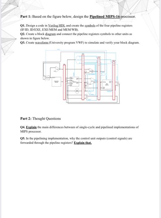
Part 1: Based on the figure below, design the Pipelined MIPS-16 processor Q1. Design a code in Verilog HDL and create the symbols of the four pipeline registers (IF/ID, ID EXE, EXE/MEM and MEM/WB). Q2. Create a block diagram and connect the pipeline registers symbols to other units as shown in figure below Q3. Create waveform (University program VWF) to simulate and verify your block diagram, - Part 2: Thought Questions 04. Explain the main differences between of single-cycle and pipelined implementations of MIPS processor Q5. In the pipelining implementation, why the control unit outputs (control signals) are forwarded through the pipeline registers? Explain that Part 1: Based on the figure below, design the Pipelined MIPS-16 processor Q1. Design a code in Verilog HDL and create the symbols of the four pipeline registers (IF/ID, ID EXE, EXE/MEM and MEM/WB). Q2. Create a block diagram and connect the pipeline registers symbols to other units as shown in figure below Q3. Create waveform (University program VWF) to simulate and verify your block diagram, - Part 2: Thought Questions 04. Explain the main differences between of single-cycle and pipelined implementations of MIPS processor Q5. In the pipelining implementation, why the control unit outputs (control signals) are forwarded through the pipeline registers? Explain that
Step by Step Solution
There are 3 Steps involved in it

Get step-by-step solutions from verified subject matter experts