

Question: PART 1 -Create a small Simulink model Create a small Simulink model to demonstrate the Scope principles of differentiation and integration using aE* omudtion sine
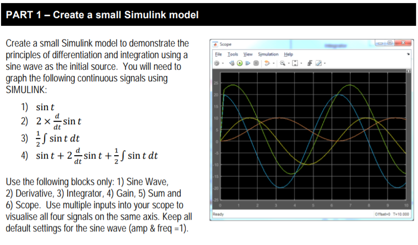
PART 1 -Create a small Simulink model Create a small Simulink model to demonstrate the Scope principles of differentiation and integration using aE* omudtion sine wave as the initial source. You will need to graph the following continuous signals using SIMULINK 25 20 1) sin t 2) 10 3) 4) 2 x frsin t J sint dt sin t +2 tsin t sin t dt Use the following blocks only: 1) Sine Wave, 2) Derivative, 3) Integrator, 4) Gain, 5) Sum and 25 6) Scope. Use multiple inputs into your scope to 10 visualise all four signals on the same axis. Keep Offset O T 10000 default settings for the sine wave (amp & freq -1). PART 1 -Create a small Simulink model Create a small Simulink model to demonstrate the Scope principles of differentiation and integration using aE* omudtion sine wave as the initial source. You will need to graph the following continuous signals using SIMULINK 25 20 1) sin t 2) 10 3) 4) 2 x frsin t J sint dt sin t +2 tsin t sin t dt Use the following blocks only: 1) Sine Wave, 2) Derivative, 3) Integrator, 4) Gain, 5) Sum and 25 6) Scope. Use multiple inputs into your scope to 10 visualise all four signals on the same axis. Keep Offset O T 10000 default settings for the sine wave (amp & freq -1)
Step by Step Solution
There are 3 Steps involved in it

Get step-by-step solutions from verified subject matter experts