

Question: Part # 1 Draw Loads ( insert resistive, Inductive, Capacitive Y or loads ) L 1 L 2 L 3 SOURCE LOAD # 1 LOAD
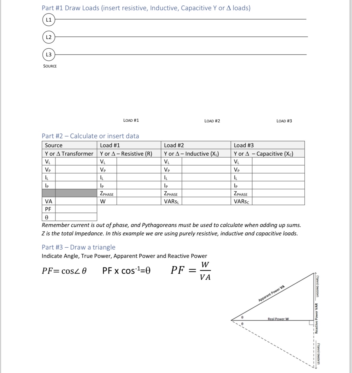
Part # Draw Loads insert resistive, Inductive, Capacitive Y or loads
L
L
L
SOURCE
LOAD #
LOAD #
LOAD #
Part # Calculate or insert data
tableSourceLoad #Load #Load #Y or Transformer,Y or Resistive RY or Inductive Y or Capacitive VVVILILILI,IpVAWVARs VARsc,PF
Remember current is out of phase, and Pythagoreans must be used to calculate when adding up sums. is the total Impedance. In this example we are using purely resistive, inductive and capacitive loads.
Part # Draw a triangle
Indicate Angle, True Power, Apparent Power and Reactive Power
Step by Step Solution
There are 3 Steps involved in it
1 Expert Approved Answer
Step: 1 Unlock

Question Has Been Solved by an Expert!
Get step-by-step solutions from verified subject matter experts
Step: 2 Unlock
Step: 3 Unlock