

Part 1: The system contains a plant (AEV) and a controller (PLC). The mechanism is divided...
Fantastic news! We've Found the answer you've been seeking!
Question:

Transcribed Image Text:
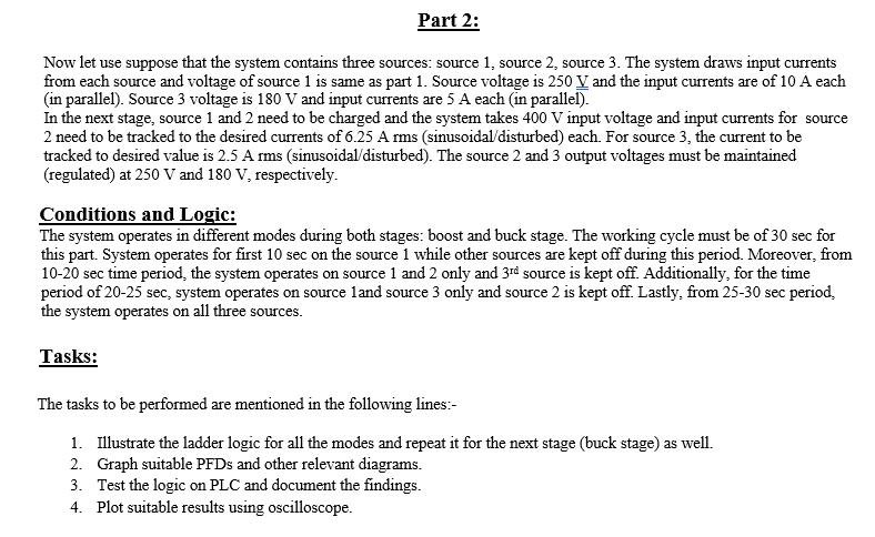
Part 1: The system contains a plant (AEV) and a controller (PLC). The mechanism is divided into two stages: boost and buck stage. Stage 1: A DC source of 220 V is connected to the plant as an input and it needs to be boosted to 400 V. Furthermore, two input current signals need to be tracked to the reference signals, respectively. The reference signal could be any sinusoidal or disturbed random signals of 14 A and both current signals are in parallel with a sum of 28 A. The output voltage needs to be regulated at 400 V constantly. Stage 2: The boost stage outputs are taken as inputs to the buck stage. Output voltage needs to be regulated (from 400 to 220 V) at 220 V during this stage and the input current signals must be tracked to the desired signals (desired or reference signals could be any disturbed signals of around 34.5 A each and must be in parallel, with a sum of 69 A). The tasks to be performed are mentioned in the following lines:- 1. Illustrate how an AEV works and label all its important parts. Also critically analyze the future of Electric Vehicles both globally and locally. 10 lines (max.). 2. Graph suitable PFDs and diagrams for each stage of the AEV. 3. Figure out the ladder logic for each stage and simulate it in software. 4. Analyze the system and control on PLC and plot suitable results for output voltage and input currents (both separate and combined) against time (optional but more than 10 seconds at least) along with the respective desired signal using an oscilloscope. Part 2: Now let use suppose that the system contains three sources: source 1, source 2, source 3. The system draws input currents from each source and voltage of source 1 is same as part 1. Source voltage is 250 V and the input currents are of 10 A each (in parallel). Source 3 voltage is 180 V and input currents are 5 A each (in parallel). In the next stage, source 1 and 2 need to be charged and the system takes 400 V input voltage and input currents for source 2 need to be tracked to the desired currents of 6.25 A rms (sinusoidal/disturbed) each. For source 3, the current to be tracked to desired value is 2.5 A rms (sinusoidal/disturbed). The source 2 and 3 output voltages must be maintained (regulated) at 250 V and 180 V, respectively. Conditions and Logic: The system operates in different modes during both stages: boost and buck stage. The working cycle must be of 30 sec for this part. System operates for first 10 sec on the source 1 while other sources are kept off during this period. Moreover, from 10-20 sec time period, the system operates on source 1 and 2 only and 3rd source is kept off. Additionally, for the time period of 20-25 sec, system operates on source 1 and source 3 only and source 2 is kept off. Lastly, from 25-30 sec period, the system operates on all three sources. Tasks: The tasks to be performed are mentioned in the following lines:- 1. Illustrate the ladder logic for all the modes and repeat it for the next stage (buck stage) as well. 2. Graph suitable PFDs and other relevant diagrams. 3. Test the logic on PLC and document the findings. 4. Plot suitable results using oscilloscope. Part 1: The system contains a plant (AEV) and a controller (PLC). The mechanism is divided into two stages: boost and buck stage. Stage 1: A DC source of 220 V is connected to the plant as an input and it needs to be boosted to 400 V. Furthermore, two input current signals need to be tracked to the reference signals, respectively. The reference signal could be any sinusoidal or disturbed random signals of 14 A and both current signals are in parallel with a sum of 28 A. The output voltage needs to be regulated at 400 V constantly. Stage 2: The boost stage outputs are taken as inputs to the buck stage. Output voltage needs to be regulated (from 400 to 220 V) at 220 V during this stage and the input current signals must be tracked to the desired signals (desired or reference signals could be any disturbed signals of around 34.5 A each and must be in parallel, with a sum of 69 A). The tasks to be performed are mentioned in the following lines:- 1. Illustrate how an AEV works and label all its important parts. Also critically analyze the future of Electric Vehicles both globally and locally. 10 lines (max.). 2. Graph suitable PFDs and diagrams for each stage of the AEV. 3. Figure out the ladder logic for each stage and simulate it in software. 4. Analyze the system and control on PLC and plot suitable results for output voltage and input currents (both separate and combined) against time (optional but more than 10 seconds at least) along with the respective desired signal using an oscilloscope. Part 2: Now let use suppose that the system contains three sources: source 1, source 2, source 3. The system draws input currents from each source and voltage of source 1 is same as part 1. Source voltage is 250 V and the input currents are of 10 A each (in parallel). Source 3 voltage is 180 V and input currents are 5 A each (in parallel). In the next stage, source 1 and 2 need to be charged and the system takes 400 V input voltage and input currents for source 2 need to be tracked to the desired currents of 6.25 A rms (sinusoidal/disturbed) each. For source 3, the current to be tracked to desired value is 2.5 A rms (sinusoidal/disturbed). The source 2 and 3 output voltages must be maintained (regulated) at 250 V and 180 V, respectively. Conditions and Logic: The system operates in different modes during both stages: boost and buck stage. The working cycle must be of 30 sec for this part. System operates for first 10 sec on the source 1 while other sources are kept off during this period. Moreover, from 10-20 sec time period, the system operates on source 1 and 2 only and 3rd source is kept off. Additionally, for the time period of 20-25 sec, system operates on source 1 and source 3 only and source 2 is kept off. Lastly, from 25-30 sec period, the system operates on all three sources. Tasks: The tasks to be performed are mentioned in the following lines:- 1. Illustrate the ladder logic for all the modes and repeat it for the next stage (buck stage) as well. 2. Graph suitable PFDs and other relevant diagrams. 3. Test the logic on PLC and document the findings. 4. Plot suitable results using oscilloscope.
Expert Answer:

Related Book For 
Automation Production Systems and Computer Integrated Manufacturing
ISBN: 978-0132393218
3rd edition
Authors: Mikell P.Groover
Posted Date:
Students also viewed these electrical engineering questions
-
An automated transfer line is divided into two stages with a storage buffer between them. Each stage consists of 9 stations. The ideal cycle time of each stage = 1.0 minute, and frequency of failure...
-
An insulated cylinder is divided into two parts of 1 m3 each by an initially locked piston. Side A has air at 200 kPa, 300 K, and side B has air at 1.0 MPa, 1000 K. The piston is now unlocked so it...
-
An insulated rigid tank is divided into two equal parts by a partition. Initially, one part contains 5 kmol of an ideal gas at 250 kPa and 40C, and the other side is evacuated. The partition is now...
-
Consider a single-output, non-preemptive queueing system. It has three queues connected to the single output, and packets in the queues are handled based on a strict-priority order. The three queues...
-
Suppose the market for bottled water and the market for soft drinks both have large numbers of buyers and sellers. Which of these markets is likely to be more competitive?
-
What is the single best capital budgeting decision criterion? Explain.
-
Coca-Cola's 2004 financial statements reported the following itemswith 2005 figures given for comparison (adapted, in millions): Compute Coca-Cola's rate of return on total assets and rate of return...
-
Paul Smith is opening a plumbing supply store in University City. He plans to sell plumbing parts and materials to both wholesale and retail customers. Since contractors (wholesale customers) prefer...
-
On 10 May an investor sells a six-month put option on 1,000 shares of a stock. The current stock price $39 and the exercise price of the put option is $40. The price of the put option is $2.30 per...
-
Elizabeth Burke has asked you to do some preliminary analysis of the data in the Performance Lawn Equipment database. First, she would like you to edit the worksheets Dealer Satisfaction and End-...
-
Using a regression analysis, I need help forecasting total losses - no incident rate or severity rate is needed. Show data, graphs and regression output. Accident Year Period Claims Frequency 5 9 10...
-
Espresso Express operates a number of espresso coffee stands in busy suburban malls. The fixed weekly expense of a coffee stand is $2,300 and the variable cost per cup of coffee served is $0.23....
-
A company produced and sold 12,200 units in its first year of operations. The sales price is $310 per unit. Fixed costs include overhead of $390,400 per year, and selling and administrative expenses...
-
Write a sub-query that returns all orders placed on the last day of activity that can be found in the Orders table. Include the orderid, orderdate, customerid, and the employeeid. #2: SUB-QUERY -...
-
The graph below shows the marginal cost of abatement curve, which shows the extra cost to the firm of cleaning up an additional unit of pollution. When a pollution charge of $5 per unit emitted is...
-
a. Calculate the change in cash and cash equivalents that occurred during 2019 b . Prepare a statement of cash flows using the indirect method. P12-4A Statement of Cash Flows (Indirect Method) TheSky...
-
= Choose values for Rc and RE so that the bias current through RE is approximately 2.1 mA and both transistor's VCE is approximately 4.9V (for quiescent analysis set V = V = 0V). Use Vcc=-VEE 15V,...
-
The Strahler Stream Order System ranks streams based on the number of tributaries that have merged. It is a top-down system where rivers of the first order are the headwaters (aka outermost...
-
What is work-in-process?
-
Name five of the ten features and capabilities of a modern CNC machine control unit listed in the text.
-
What is an automated guided vehicle system (AGVS)?
-
Continuing Problem 13, the string is stretched to the position shown in Figure 2.45. Calculate the natural frequency of the system using the following parameter values: \(m g=2 \mathrm{lb}, T=50...
-
Derive the equation of motion for a uniform stiff rod restrained from vertical motion by a torsional spring of stiffness \(K\) and two translational springs each of stiffness \(k\), as shown in...
-
A uniform rigid and massless rod is pinned at one end and connected to ground via a spring at the other end. At midpoint on the rod, a spring is connected to a mass which is connected to a fixed...

Study smarter with the SolutionInn App