

Question: Part 1-Create the Network and Configure the Interfaces (20 Points) 1. Open Packet Tracer and create a new network with the following hardware a. 1-MultiLayer
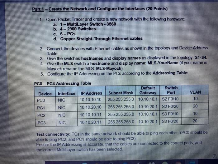
Part 1-Create the Network and Configure the Interfaces (20 Points) 1. Open Packet Tracer and create a new network with the following hardware a. 1-MultiLayer Switch - 3560 b. 4-2960 Switches c. 6-PCs d. Copper Straight-Through Ethernet cables 2. Connect the devices with Ethemet cables as shown in the topology and Device Address Table. 3. Give the switches hostnames and display names as displayed in the topology S1-54. 4. Give the MLS switch a hostname and display name: MLS-YourName (if your name is Mayock rename the MLS MLS-Mayock) 5. Configure the IP Addressing on the PCs according to the Addressing Table: PCO - PC4 Addressing Table Default Switch Device Interface IP Address Subnet Mask Gateway Port VLAN PCO NIC 10.10 10.10 255.255.255.0 10.10.10.1 S2 F0/10 10 PC1 NIC 10.10.20.10 255.255.255.0 10.10.20.1 S2 F0/20 20 PC2 NIC 10 10.10.11 255 255 255.0 10 10.10.1 S3 F0/10 10 PC3 NIC 10.10.2011 255.255.255.0 10.10.20.1 S3 F0/20 20 Test connectivity: PCs in the same network should be able to ping each other (PCO should be able to ping PC2 and PC1 should be able to ping PC3) Ensure the IP Addressing is accurate that the cables are connected to the correct ports, and the correct Multilayer switch has been selected Part 1-Create the Network and Configure the Interfaces (20 Points) 1. Open Packet Tracer and create a new network with the following hardware a. 1-MultiLayer Switch - 3560 b. 4-2960 Switches c. 6-PCs d. Copper Straight-Through Ethernet cables 2. Connect the devices with Ethemet cables as shown in the topology and Device Address Table. 3. Give the switches hostnames and display names as displayed in the topology S1-54. 4. Give the MLS switch a hostname and display name: MLS-YourName (if your name is Mayock rename the MLS MLS-Mayock) 5. Configure the IP Addressing on the PCs according to the Addressing Table: PCO - PC4 Addressing Table Default Switch Device Interface IP Address Subnet Mask Gateway Port VLAN PCO NIC 10.10 10.10 255.255.255.0 10.10.10.1 S2 F0/10 10 PC1 NIC 10.10.20.10 255.255.255.0 10.10.20.1 S2 F0/20 20 PC2 NIC 10 10.10.11 255 255 255.0 10 10.10.1 S3 F0/10 10 PC3 NIC 10.10.2011 255.255.255.0 10.10.20.1 S3 F0/20 20 Test connectivity: PCs in the same network should be able to ping each other (PCO should be able to ping PC2 and PC1 should be able to ping PC3) Ensure the IP Addressing is accurate that the cables are connected to the correct ports, and the correct Multilayer switch has been selected
Step by Step Solution
There are 3 Steps involved in it

Get step-by-step solutions from verified subject matter experts