

Question: Part 2 : Design the four bar linkage in the rear suspension system of the bicycle shown below. Link names are as indicated next to
Part :
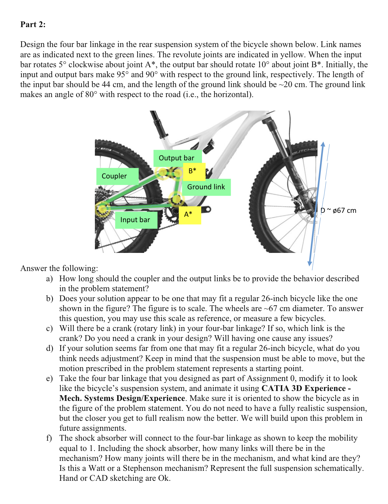
Design the four bar linkage in the rear suspension system of the bicycle shown below. Link names are as indicated next to the green lines. The revolute joints are indicated in yellow. When the input bar rotates circ clockwise about joint A the output bar should rotate circ about joint B Initially, the input and output bars make circ and circ with respect to the ground link, respectively. The length of the input bar should be cm and the length of the ground link should be sim mathrm~cm The ground link makes an angle of circ with respect to the road ie the horizontal
Answer the following:
a How long should the coupler and the output links be to provide the behavior described in the problem statement?
b Does your solution appear to be one that may fit a regular inch bicycle like the one shown in the figure? The figure is to scale. The wheels are sim mathrm~cm diameter. To answer this question, you may use this scale as reference, or measure a few bicycles.
c Will there be a crank rotary link in your fourbar linkage? If so which link is the crank? Do you need a crank in your design? Will having one cause any issues?
d If your solution seems far from one that may fit a regular inch bicycle, what do you think needs adjustment? Keep in mind that the suspension must be able to move, but the motion prescribed in the problem statement represents a starting point.
e Take the four bar linkage that you designed as part of Assignment modify it to look like the bicycle's suspension system, and animate it using CATIA D Experience Mech. Systems DesignExperience Make sure it is oriented to show the bicycle as in the figure of the problem statement. You do not need to have a fully realistic suspension, but the closer you get to full realism now the better. We will build upon this problem in future assignments.
f The shock absorber will connect to the fourbar linkage as shown to keep the mobility equal to Including the shock absorber how many links will there be in the mechanism? How many joints will there be in the mechanism, and what kind are they? Is this a Watt or a Stephenson mechanism? Represent the full suspension schematically. Hand or CAD sketching are Ok
Step by Step Solution
There are 3 Steps involved in it
1 Expert Approved Answer
Step: 1 Unlock

Question Has Been Solved by an Expert!
Get step-by-step solutions from verified subject matter experts
Step: 2 Unlock
Step: 3 Unlock