

Question: Part 3: unknown Circuit B R 565.n 385, 385, M On 565-ML 635, 635_ MBR TOTAL R: 564 nLab total of 3 unique circuits. Predict
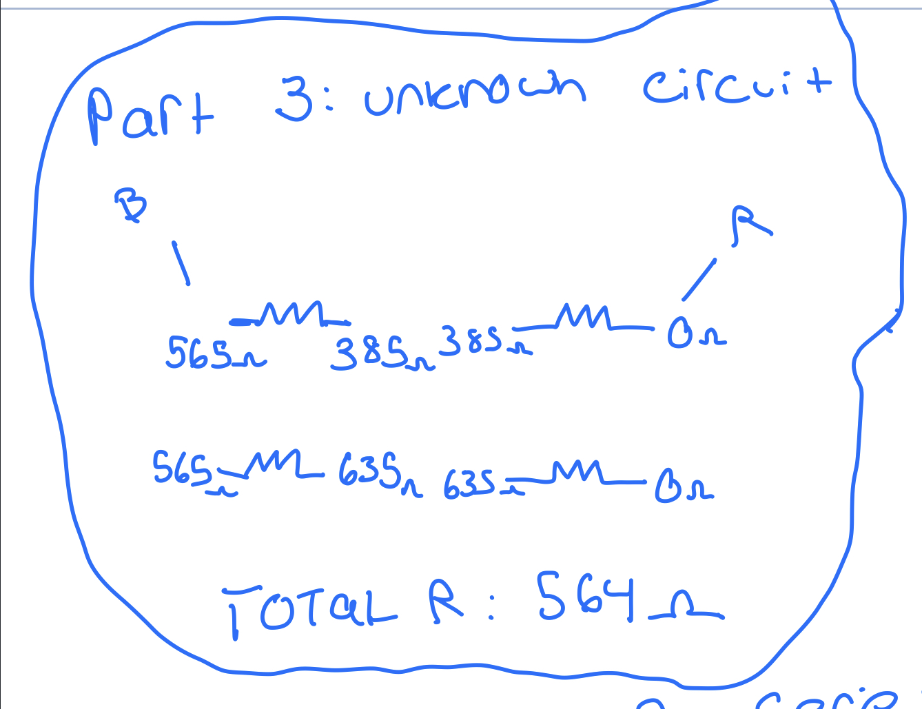
Part 3: unknown Circuit B R 565.n 385, 385, M On 565-ML 635, 635_ MBR TOTAL R: 564 nLab total of 3 unique circuits. Predict the resistance for each D10 File of the combinations, these predications should be entered X in your lab notebook and lab report. Document your C reasoning. Set up the combinations on a prototyping board and measure the total resistance of the combinations. Compare your predictions to the results in a detail as part Figure 5 Series Pair in Parallel Part 3: Unknown Circuit measurements of your lab report. Circuit number C) More complex circuits. Before setting up the circuits in this part draw diagrams and answer the questions based on your predictions. Using all four of your resistors, construct a series combination of two parallel circuits and a parallel combination of two series. Make predictions about each of the following questions and then as part of your report compare your results to the measurements. Which of your circuits will have the larger resistance or will they be the same? Is there a general rule or does it depend on the specific resistors and their respective places? Set up each of your two circuits and make measurements of resistance. With the last two questions in mind move your resistors around to prove or disprove your answers. It may surprise you that there are only three of each type that are unique, sketch all 6 and check them by setting them up Part III: The Unknown Circuit Hint 1: Choose to work with either voltages or resistances. Hint 2: Draw a diagram and add connections as you determine them. Hint 3: Any points with a zero resistance or potential difference are attached to each other. You will be assigned an unknown circuit. You should record the number for your report. Your task is to make measurements and determine the structure of the circuit; you cannot do this by simply looking at the circuit as all the wiring is hidden from view. You may not take apart the circuit to determine the structure. You should create a diagram that corresponds to your conclusion. You should include your measurements and describe your logic in your report. Hint, you can apply a small voltage and measure the voltage differences between points. Part 3 Part 2 Part 1 + Midterm Bic Page 5 of 5 1340 words X English (United States) Focus + 126% Ready b FEB 28 4 S Lo
Step by Step Solution
There are 3 Steps involved in it

Get step-by-step solutions from verified subject matter experts