

Question: Part A What can you conclude from your recorded observations? Address the following questions: Why does moving the magnet result in a deflection of the
Part A
- What can you conclude from your recorded observations?
Address the following questions: Why does moving the magnet result in a
deflection of the galvanometer? How does the direction of the movement
affect the direction of deflection?
Part B
- What can you conclude form your recorded observations? What does the iron core do? Can you now explain the purpose of using an iron core in a transformer?
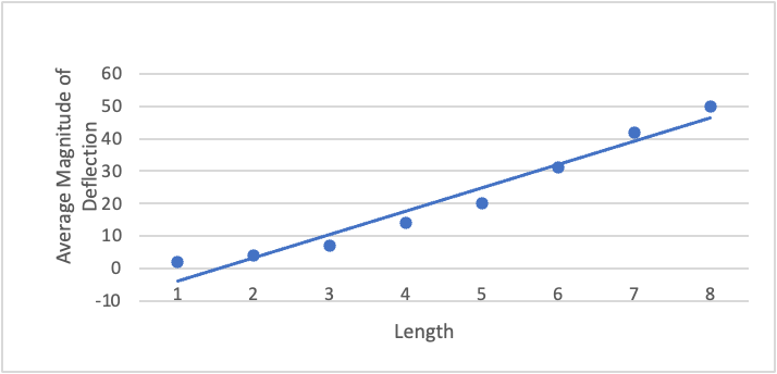
- Graph of average deflection vs decreasing length inside the coil
Part C
- What does the graph imply about the relationship between these two quantities? Does this make sense i.e. is it in keeping with the theory of Electromagnetic Induction?
DISCUSSION AND COMMENTS
- What are possible sources of error in this lab?
- Use your deductions from this lab to answer the following question. A bar magnet is dropped through a horizontal loop of wire connected to a galvanometer. The North pole of the magnet is closer to the wire. Describe what you would observe on the galvanometer as the magnet approaches the loop and exits the loop.
PLEASE HELP WITH WITH PART A,B,C AND DISCUSSION QUESTIONS ONTOP. THE LAB, TABLE, GRAPHS AND RESULTS ARE BELOW.
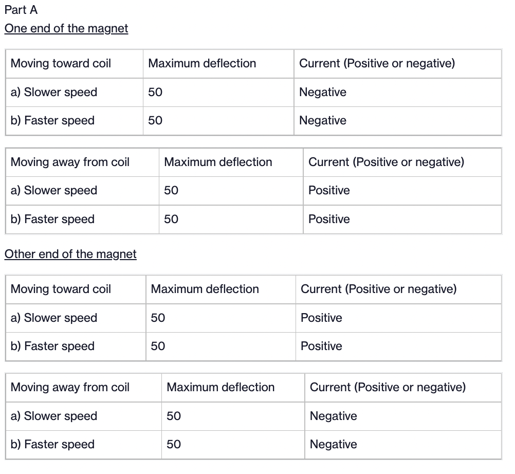
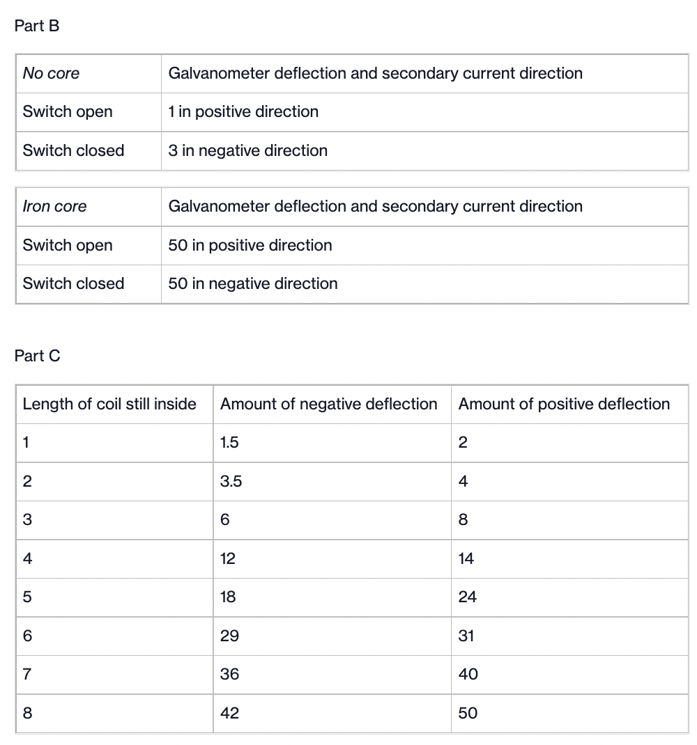
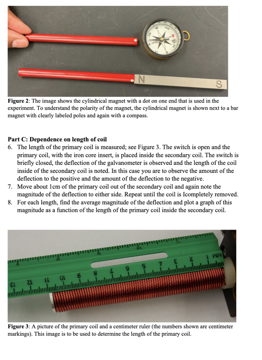
Part A One end of the magnet Moving toward coil Maximum deflection Current (Positive or negative) a) Slower speed 50 Negative b) Faster speed 50 Negative Moving away from coil Maximum deflection Current (Positive or negative) a) Slower speed 50 Positive b) Faster speed 50 Positive Other end of the magnet Moving toward coil Maximum deflection Current (Positive or negative) a) Slower speed 50 Positive b) Faster speed 50 Positive Moving away from coil Maximum deflection Current (Positive or negative) a) Slower speed 50 Negative b) Faster speed 50 Negative\fPart B No core Galvanometer deflection and secondary current direction Switch open 1 in positive direction Switch closed 3 in negative direction iron core Galvanometer deflection and secondary current direction Switch open 50 in positive direction Switch closed 50 in negative direction Part C Length of coil still inside Amount of negative deflection Amount of positive deflection 1 1.5 2 2 3.5 4 3 6 8 4 12 14 5 18 24 6 29 31 7 36 4o 8 42 50 N S Figure 2: The image shows the cylindrical magnet with a dot on one end that is used in the experiment. To understand the polarity of the magnet, the cylindrical magnet is shown next to a bar magnet with clearly labeled poles and again with a compass. Part C: Dependence on length of coil 6. The length of the primary coil is measured; see Figure 3. The switch is open and the primary coil, with the iron core insert, is placed inside the secondary coil. The switch is briefly closed, the deflection of the galvanometer is observed and the length of the coil inside of the secondary coil is noted. In this case you are to observe the amount of the deflection to the positive and the amount of the deflection to the negative. 7. Move about Icm of the primary coil out of the secondary coil and again note the magnitude of the deflection to either side. Repeat until the coil is Icompletely removed. 8. For each length, find the average magnitude of the deflection and plot a graph of this magnitude as a function of the length of the primary coil inside the secondary coil. IN CHINA LL OL 6 8 12 13 Figure 3: A picture of the primary coil and a centimeter ruler (the numbers shown are centimeter markings). This image is to be used to determine the length of the primary coil.Lab Procedure : Electromagnetic Induction Objective: Is to observe the induced current by a changing magnetic field and understand the direction of the induced current. You will observe how the rate of change of magnetic flux through the coil can affect the induced emf voltage. EQUIPMENT NEEDED: . compass . Insulated cylindrical coil . PASCO Wireless Voltage Sensor' . Strong magnet, cylindrical . 4-mm banana plug patch cord with . Galvanometer alligator clip' (2) . Iron core rod Procedure: Part A: Induced current 1. Connect the galvanometer to the ends of the coil as shown in the Figure. Bring the magnet toward and insert the magnet in to the coil while making note of the deflection of the galvanometer. You are not looking for specific numbers but you are noting the amount of the deflection and the direction of the deflection. Document your observations. It is important to understand which pole is VOLTMETER represented by the end of the magnet with the dot. See Figure 2 below that shows the red cylindrical magnet, used in the experiment, in proximity to a labelled bar magnet and a compass. Figure 1: The figure 2. Repeat the process while moving the magnet into the coil at shows the experimental increasing speed and then at decreasing speed. Again, setup for determining the record your observations. induced current. 3. Lastly, flip the magnet so that you are now bringing the other pole of the magnet toward and into the coil. Document your observations. What conclusions can you make? Part B: Permeability 4. Now, connect the primary coil to a power supply but keep the switch open, the secondary coil remains connected to the galvanometer. Close and open the switch, make a note of the amount and direction of the deflection of the galvanometer in each case. 5. Repeat Step 4 with the metal core inserted into the primary coil
Step by Step Solution
There are 3 Steps involved in it

Get step-by-step solutions from verified subject matter experts