

Question: PART B: KIRCHHOFF'S CURRENT LAW 1 . Construct the circuit as shown in Figure 2 . 4 and set the power supply voltage to 1
PART B: KIRCHHOFF'S CURRENT LAW
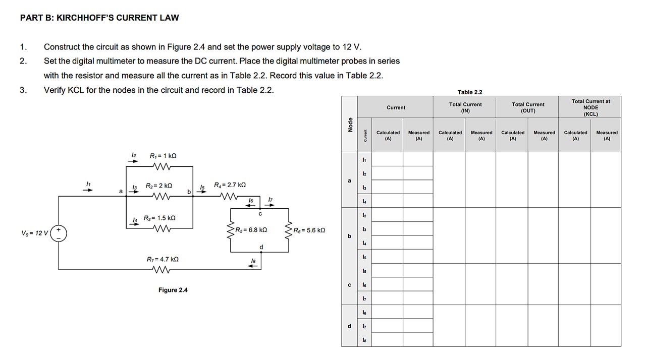
Construct the circuit as shown in Figure and set the power supply voltage to V
Set the digital multimeter to measure the DC current. Place the digital multimeter probes in series with the resistor and measure all the current as in Table Record this value in Table
Verify KCL for the nodes in the circuit and record in Table
Table
begintabularcccccccccc
hline multirow
beginarrayl
text
text z
endarray
& multicolumncCurrent & multicolumnlbegintabularl
Total Current
IN
endtabular & multicolumnlTotal Current OUT & multicolumnlTotal Current at NODE KCL
hline & & begintabularl
Calculated
A
endtabular & begintabularl
Measured
A
endtabular & begintabularl
Calculated
A
endtabular & begintabularl
Measured
A
endtabular & begintabularl
Calculated
A
endtabular & begintabularl
Measured
A
endtabular & begintabularl
Calculated
A
endtabular & begintabularl
Measured
A
endtabular
hline multirowta & & & & & & & & &
hline & & & & & & & & &
hline multirowb
c & begintabularl
I
I
endtabular & & & & & & & &
hline & multirowtbegintabularl
mathrmI
Is
I
endtabular & & & & & & & &
hline & & & & & & & & &
hline & & & & & & & & &
hline multirowbd & & & & & & & & &
hline & begintabularl
mathrmI
mathrmI
endtabular & & & & & & & &
hline
endtabular
Step by Step Solution
There are 3 Steps involved in it
1 Expert Approved Answer
Step: 1 Unlock

Question Has Been Solved by an Expert!
Get step-by-step solutions from verified subject matter experts
Step: 2 Unlock
Step: 3 Unlock