

Question: Part II: Modifying the Counter for additional functionality. In this section we will add some additional functionality to the counter. 1 . ) Our first
Part II: Modifying the Counter for additional functionality.
In this section we will add some additional functionality to the counter.
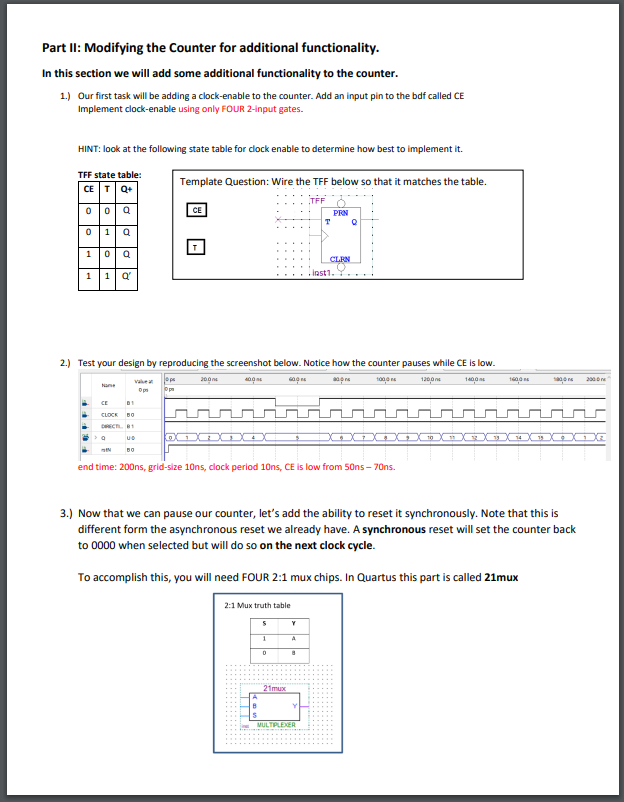
Our first task will be adding a clockenable to the counter. Add an input pin to the bdf called CE
Implement clockenable using only FOUR input gates.
HINT: look at the following state table for clock enable to determine how best to implement it
TFF state table:
Template Question: Wire the TFF below so that it matches the table.
Test your design by reproducing the screenshot below. Notice how the counter pauses while CE is low.
end time: gridsize ns clock period CE is low from ns ns
Now that we can pause our counter, let's add the ability to reset it synchronously. Note that this is
different form the asynchronous reset we already have. A synchronous reset will set the counter back
to when selected but will do so on the next clock cycle.
To accomplish this, you will need FOUR : mux chips. In Quartus this part is called mux
Step by Step Solution
There are 3 Steps involved in it
1 Expert Approved Answer
Step: 1 Unlock

Question Has Been Solved by an Expert!
Get step-by-step solutions from verified subject matter experts
Step: 2 Unlock
Step: 3 Unlock