

Question: PathSim Lab Observing Data Flow within the MIPS Processor Goal: With the completion of this lab you will understand the values placed on lines in
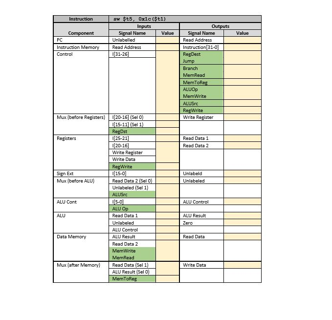
PathSim Lab Observing Data Flow within the MIPS Processor Goal: With the completion of this lab you will understand the values placed on lines in the data path for the R-type instructions as discussed in sections 4.1 through 4.4 Steps: Open PathSim by running its jar file PathSim.jar Select and copy the snippet of assembly code appearing below and paste it into the Assembly Code textarea of PathSim. You can do some text-editing within this area. Assemble the set of instructions by pressing the Assemble button. The snippet of code is written intentionally with two syntax errors. Thus, when you assemble the code, an alert box will popup, showing a line containing an error. The PathSim assembler isa "first error and out" assembler and, therefore, you will only see one error at a time Now, fix the first error and (re-jassemble the edited code. Since there is another error in the code, you will see another alert box showing the second error. Fix the second error, assemble the edited code and it should now assemble successfully. If another error should appear and on the last line, it is due to a missing end-of-line marker. PathSim expects that ALL lines are terminated with an end-of-line Select and copy the three lines of words with addresses in the Data Memory section below and paste it into the Data Input textarea. Press the Load Memory button and the data should load successfully. If not, check to see that there are no empty lines nor spaces within the text. Also, make sure the third line is terminated with an end-of-line marker Select and copy the one word with register number appearing in Register Values section below and paste it into Register Input. Press the Load button appearing below the Register Input area; the word should load successfully into the specified register. If not, make sure that the line is terminated with an end-of-line marker and there are not empty lines nor spaces. 1. 2. 3. 4. 5. 6. Press the "Reset Machine" button. 7. Place the mouse over the rectangle marked PC shown in the data path diagram and left click the mouse. Left-clicking on PC steps through the machine instructions that were assembled from the snippet of assembly code, one instruction per click. As you step through the code, place the mouse over data lines shown in the data path diagram and left-click the mouse. A popup box will appear showing the value which is on that line. Observe the values placed on data lines as you step through each of the following instructions. Record the values in the yellow fields of the table given at the end of this document. The green fields indicate signals. Make sure you also understand how the values are established for all instructions. 8. a. Iw $ao, 0(?t1) b. add $t2, $a0, $a1 PathSim Lab Observing Data Flow within the MIPS Processor Goal: With the completion of this lab you will understand the values placed on lines in the data path for the R-type instructions as discussed in sections 4.1 through 4.4 Steps: Open PathSim by running its jar file PathSim.jar Select and copy the snippet of assembly code appearing below and paste it into the Assembly Code textarea of PathSim. You can do some text-editing within this area. Assemble the set of instructions by pressing the Assemble button. The snippet of code is written intentionally with two syntax errors. Thus, when you assemble the code, an alert box will popup, showing a line containing an error. The PathSim assembler isa "first error and out" assembler and, therefore, you will only see one error at a time Now, fix the first error and (re-jassemble the edited code. Since there is another error in the code, you will see another alert box showing the second error. Fix the second error, assemble the edited code and it should now assemble successfully. If another error should appear and on the last line, it is due to a missing end-of-line marker. PathSim expects that ALL lines are terminated with an end-of-line Select and copy the three lines of words with addresses in the Data Memory section below and paste it into the Data Input textarea. Press the Load Memory button and the data should load successfully. If not, check to see that there are no empty lines nor spaces within the text. Also, make sure the third line is terminated with an end-of-line marker Select and copy the one word with register number appearing in Register Values section below and paste it into Register Input. Press the Load button appearing below the Register Input area; the word should load successfully into the specified register. If not, make sure that the line is terminated with an end-of-line marker and there are not empty lines nor spaces. 1. 2. 3. 4. 5. 6. Press the "Reset Machine" button. 7. Place the mouse over the rectangle marked PC shown in the data path diagram and left click the mouse. Left-clicking on PC steps through the machine instructions that were assembled from the snippet of assembly code, one instruction per click. As you step through the code, place the mouse over data lines shown in the data path diagram and left-click the mouse. A popup box will appear showing the value which is on that line. Observe the values placed on data lines as you step through each of the following instructions. Record the values in the yellow fields of the table given at the end of this document. The green fields indicate signals. Make sure you also understand how the values are established for all instructions. 8. a. Iw $ao, 0(?t1) b. add $t2, $a0, $a1
Step by Step Solution
There are 3 Steps involved in it

Get step-by-step solutions from verified subject matter experts