

Question: PC-PT PCD Switch-PT Switch0 2811 Router1 2011 Router Switch-PT Switch2 PC-PT PC2 2811 Router2 Switch PT Switch1 PC-PT PC1 Figure 2: Packet Tracer Network
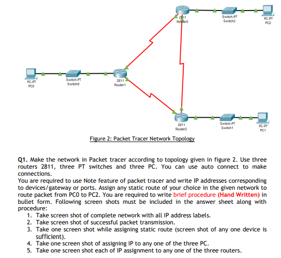
PC-PT PCD Switch-PT Switch0 2811 Router1 2011 Router Switch-PT Switch2 PC-PT PC2 2811 Router2 Switch PT Switch1 PC-PT PC1 Figure 2: Packet Tracer Network Topology Q1. Make the network in Packet tracer according to topology given in figure 2. Use three routers 2811, three PT switches and three PC. You can use auto connect to make connections. You are required to use Note feature of packet tracer and write IP addresses corresponding to devices/gateway or ports. Assign any static route of your choice in the given network to route packet from PCO to PC2. You are required to write brief procedure (Hand Written) in bullet form. Following screen shots must be included in the answer sheet along with procedure: 1. Take screen shot of complete network with all IP address labels. 2. Take screen shot of successful packet transmission. 3. Take one screen shot while assigning static route (screen shot of any one device is sufficient). 4. Take one screen shot of assigning IP to any one of the three PC. 5. Take one screen shot each of IP assignment to any one of the three routers.
Step by Step Solution
There are 3 Steps involved in it

Get step-by-step solutions from verified subject matter experts