

Question: PHYS 1415 LabO7: Series and Parallel Circuits Objectives: 0 To explore various arrangements of batteries and bulbs, and the effect of those arrangements on bulb
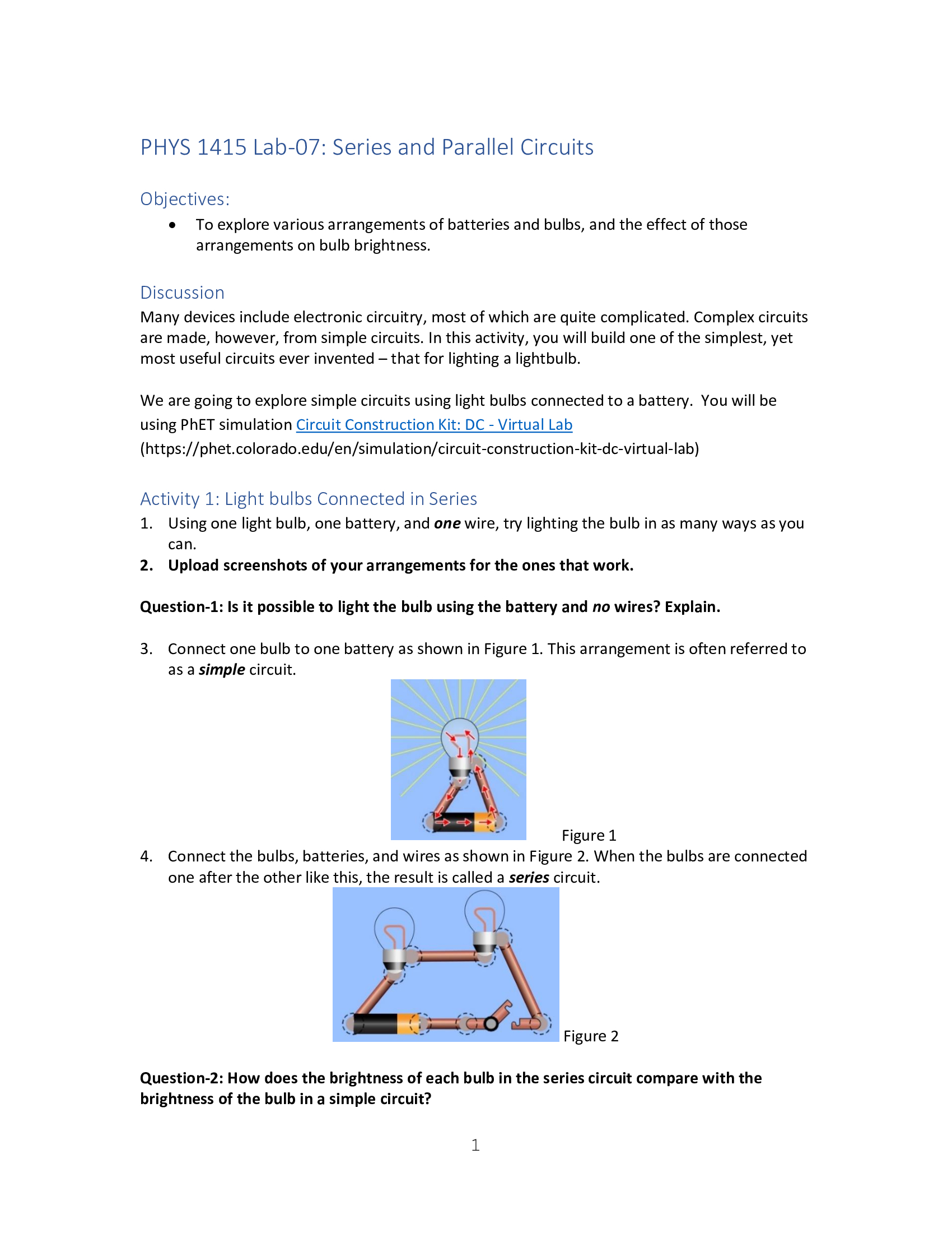
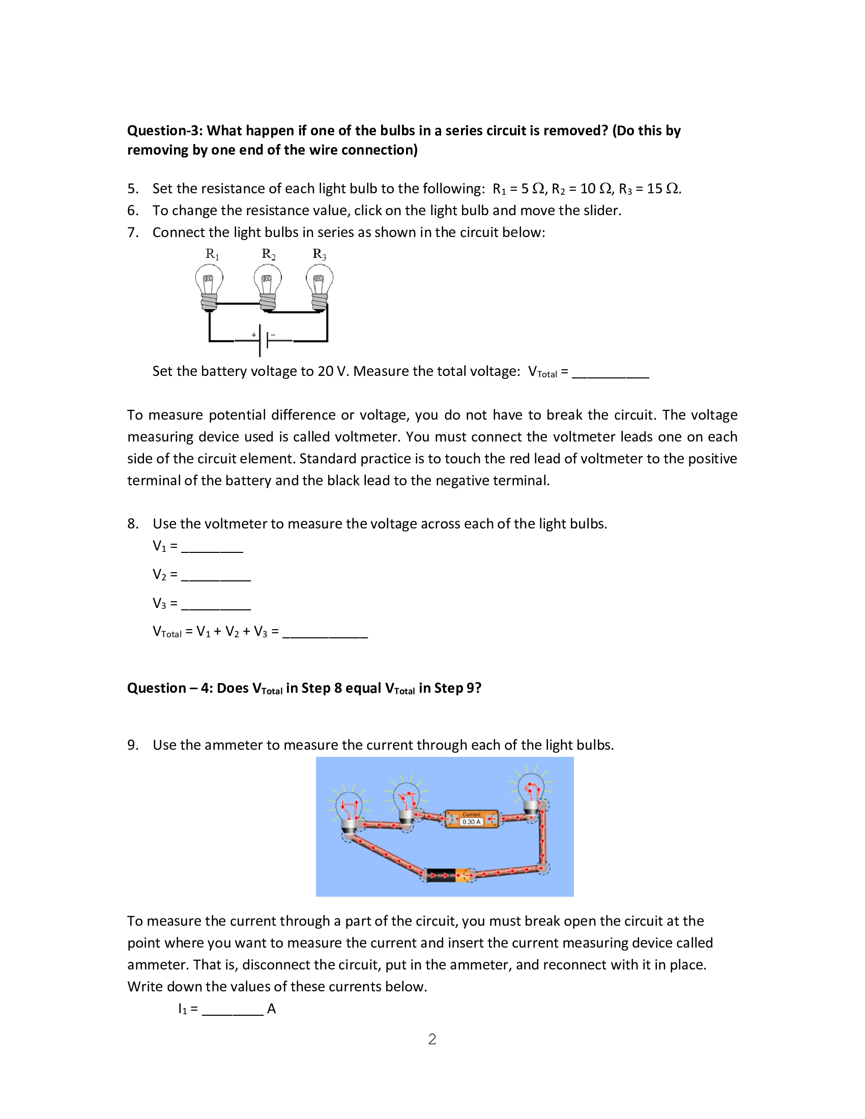
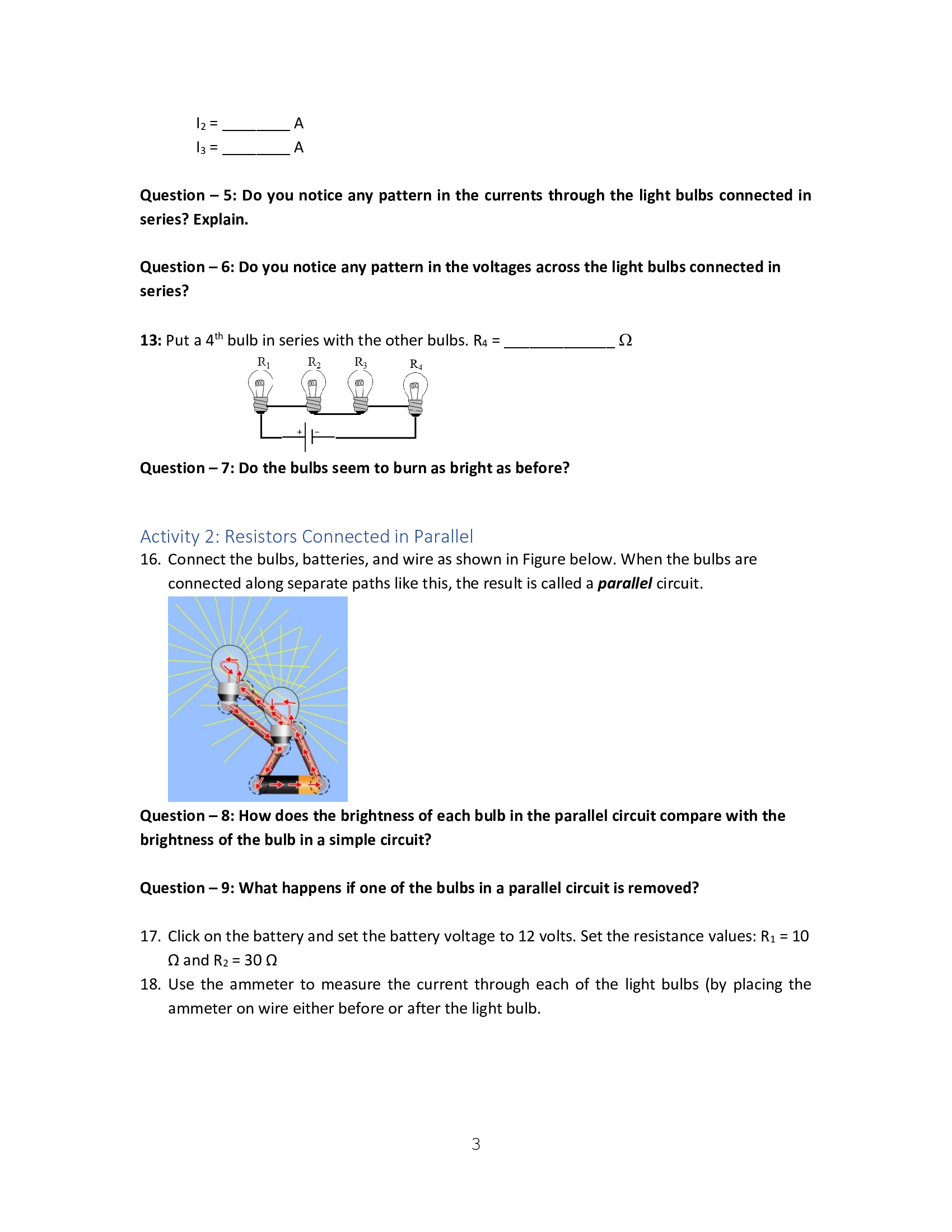
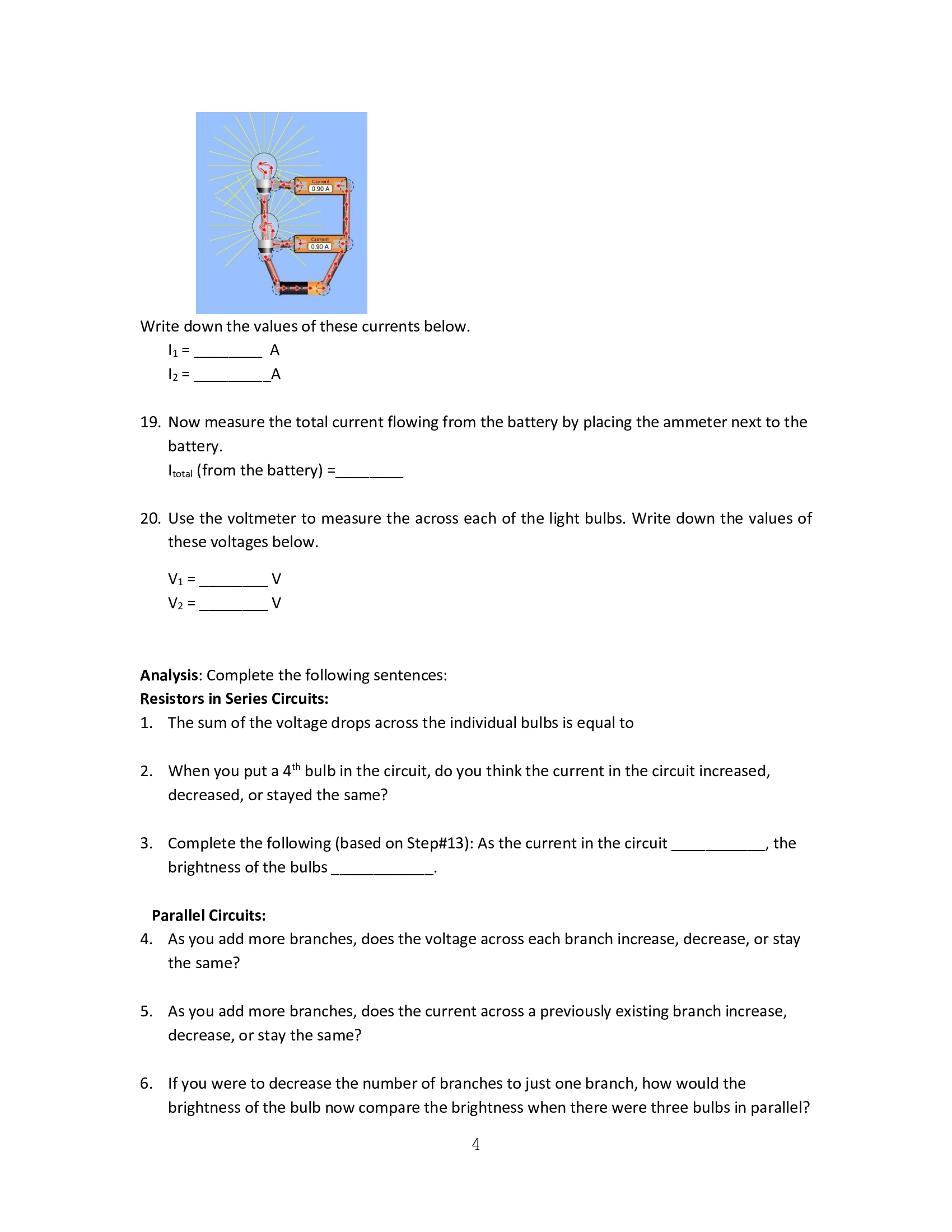

PHYS 1415 LabO7: Series and Parallel Circuits Objectives: 0 To explore various arrangements of batteries and bulbs, and the effect of those arrangements on bulb brightness. Discussion Many devices include electronic circuitry, most of which are quite complicated. Complex circuits are made, however, from simple circuits. In this activity, you will build one of the simplest, yet most useful circuits ever invented that for lighting a lightbulb. We are going to explore simple circuits using light bulbs connected to a battery. You will be using PhET simulation Circuit Construction Kit: DC Virtual Lab (https://phet.colorado.edu/en/simulation/circuit-construction-kit-dc-virtual-lab) Activity 1: Light bulbs Connected in Series 1. Using one light bulb, one battery, and one wire, try lighting the bulb in as many ways as you can. 2. Upload screenshots of your arrangements for the ones that work. Question-1: Is it possible to light the bulb using the battery and no wires? Explain. 3. Connect one bulb to one battery as shown in Figure 1. This arrangement is often referred to as a simple circuit. Figure 1 4. Connect the bulbs, batteries, and wires as shown in Figure 2. When the bulbs are connected one after the other like this, the result is called a series circuit. .- 7. ' : g i ' f i' [u ~-I ' I . -Z ::J : '5 \\'- s- '-.' Question-2: How does the brightness of each bulb in the series circuit compare with the brightness of the bulb in a simple circuit? Figure 2 Question-3: What happen if one of the bulbs in a series circuit is removed? (Do this by removing by one end of the wire connection) 5. Set the resistance of each light bulb to the following: R1 = 5 (2, R2 = 10 (2, R3 = 15 Q. 6. To change the resistance value, click on the light bulb and move the slider. 7. Connect the light bulbs in series as shown in the circuit below: R R 1 2 R3 so so .,.. +|I- Set the battery voltage to 20 V. Measure the total voltage: VTm. = _ To measure potential difference or voltage, you do not have to break the circuit. The voltage measuring device used is called voltmeter. You must connect the voltmeter leads one on each side of the circuit element. Standard practice is to touch the red lead of voltmeter to the positive terminal of the battery and the black lead to the negative terminal. 8. Use the voltmeter to measure the voltage across each of the light bulbs. VTotal = V1 + V2 + V3 = _ __ Question 4: Does Vma. in Step 8 equal Vma. in Step 9? 9. Use the ammeter to measure the current through each of the light bulbs. To measure the current through a part of the circuit, you must break open the circuit at the point where you want to measure the current and insert the current measuring device called ammeter. That is, disconnect the circuit, put in the ammeter, and reconnect with it in place. Write down the values of these currents below. I1 = A Question 5: Do you notice any pattern in the currents through the light bulbs connected in series? Explain. Question 6: Do you notice any pattern in the voltages across the light bulbs connected in series? 13: Put a 4th bulb in series with the other bulbs. R4 = _ _ 2 11, R2 R3 R, f} (A / 3 v\" iml l Question 7: Do the bulbs seem to burn as bright as before? Activity 2: Resistors Connected in Parallel 16. Connect the bulbs, batteries, and wire as shown in Figure below. When the bulbs are connected along separate paths like this, the result is called a parallel circuit. Question 8: How does the brightness of each bulb in the parallel circuit compare with the brightness of the bulb in a simple circuit? Question 9: What happens if one of the bulbs in a parallel circuit is removed? 17. Click on the battery and set the battery voltage to 12 volts. Set the resistance values: R1 = 10 Q and R2 = 30 Q 18. Use the ammeter to measure the current through each of the light bulbs (by placing the ammeter on wire either before or after the light bulb. 19. Now measure the total current flowing from the battery by placing the ammeter next to the battery. Imta. (from the battery) : 20. Use the voltmeter to measure the across each of the light bulbs. Write down the values of these voltages below. Analysis: Complete the following sentences: Resistors in Series Circuits: 1. The sum of the voltage drops across the individual bulbs is equal to 2. When you put a 4th bulb in the circuit, do you think the current in the circuit increased, decreased, or stayed the same? 3. Complete the following (based on Step#13): As the current in the circuit the brightness of the bulbs Parallel Circuits: 4. As you add more branches, does the voltage across each branch increase, decrease, or stay the same? 5. As you add more branches, does the current across a previously existing branch increase, decrease, or stay the same? 6. If you were to decrease the number of branches to just one branch, how would the brightness of the bulb now compare the brightness when there were three bulbs in parallel? 4 How do you suppose most of the circuits in your home are wired in series or in parallel? What is your evidence. How do you suppose automobile headlights are wired in series or in parallel? What is your evidence
Step by Step Solution
There are 3 Steps involved in it

Get step-by-step solutions from verified subject matter experts