

Question: Physics Parallel and Series Circuit Lab Use references from Part A and data (Values and photos) from Part B in the lab to answer questions


Physics Parallel and Series Circuit Lab
Use references from Part A and data (Values and photos) from Part B in the lab to answer questions in Part C
There are 3 parts in this lab :
Part 1: One resistor circuits
Part 2: Series circuits with resistors
Part 3: Parallel circuits with resistors
Part A: References (Protocol)
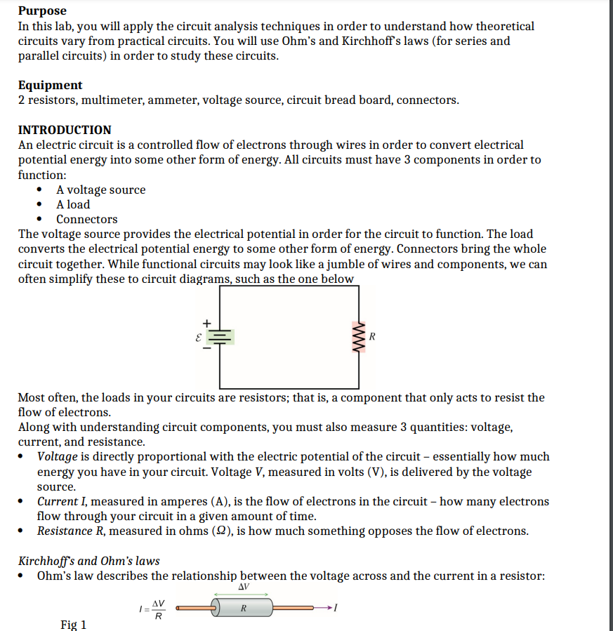


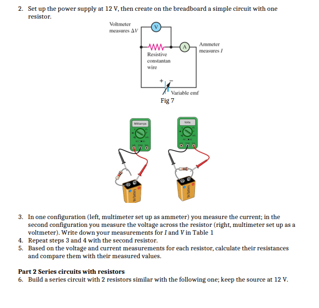


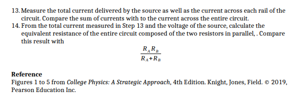
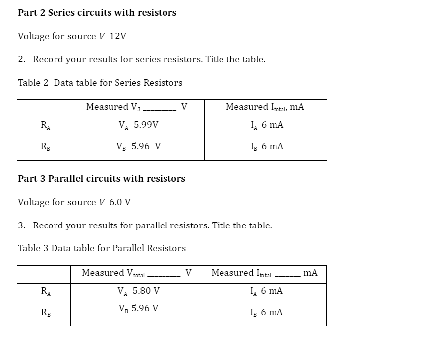
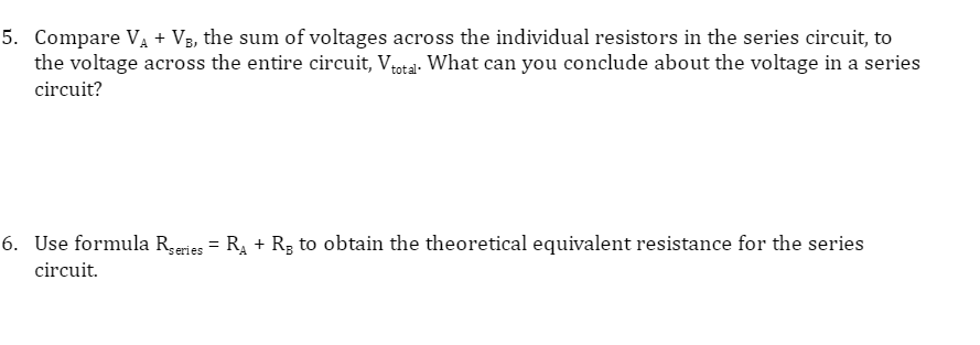

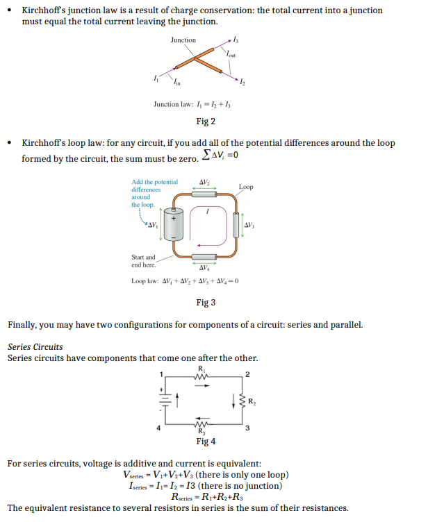
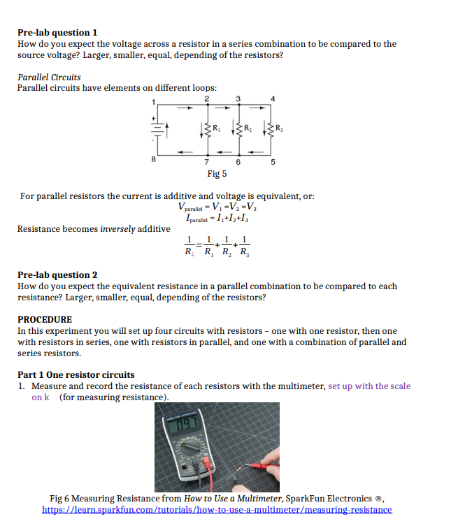
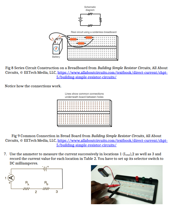
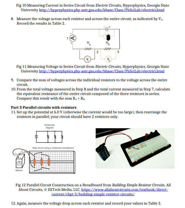
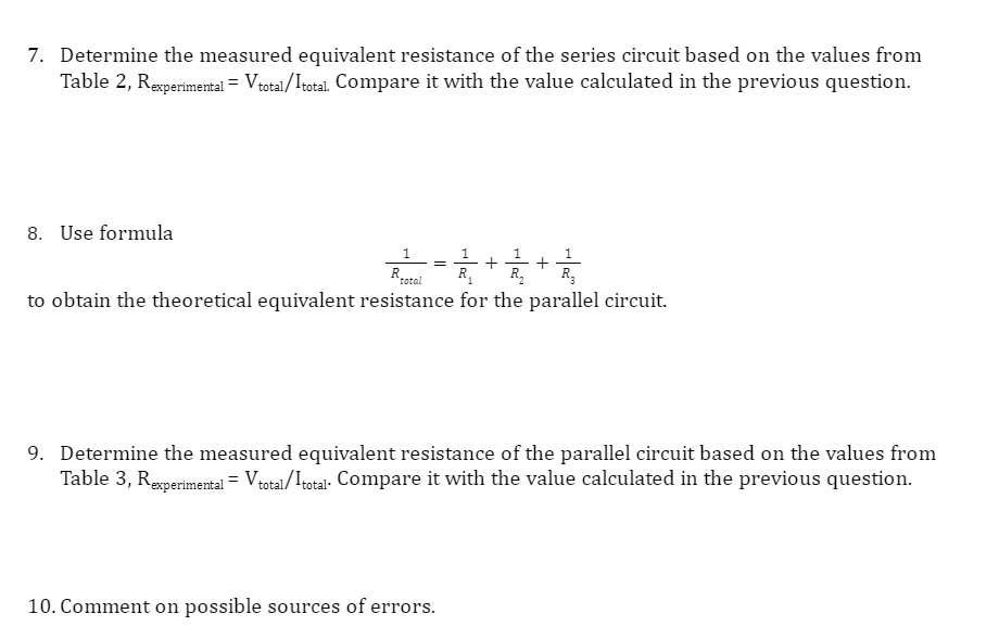
Purpose In this lab, you will apply the circuit analysis techniques in order to understand how theoretical circuits vary from practical circuits. You will use Dhm's and Kirchhoffs laws (for series and parallel circuits) in order to study these circuits. Equipment 2 resistors. multimeter. ammeter. voltage source. circuit bread board. connectors. INTRODUCTION An electric circuit is a controlled ow of electrons through wires in order to convert electrical potential energy into some other form of energy. All circuits must have 3 components in order to function: 1' Avoltage source - Aload - Connectors The voltage source provides the electrical potential in order for the circuit to function. The load converts the electrical potential energy to some other form of energy. Connectors bring the whole circuit together. While functional circuits may look like a jumble of wires and components. we can often simplify these to circuit diagrams, such as the one below Most often. the loads in your circuits are resistors; that is, a component that only acts to resist the flow of electrons. Along with understanding circuit components. you must also measure 3 quantities: voltage. current. and resistance. It Voltage is directly proportional with the electric potential of the circuit essentially how much energy you have in your circuit. Voltage V, measured in volts (V), is delivered by the voltage source. ' Current I. measured in amperes (AL is the flow of electrons in the circuit how many electrons ow through your circuit in a given amount of time. It Resistance R. measured in ohms {9). is how much something opposes the flow of electrons. Kirchhos and Uhm's laws ' Dhm's law describes the relationship between the voltage across and the current in a resistor: s1! Fig 1 Kirchhoff's junction law is a result of charge conservation: the total current into a junction must equal the total current leaving the junction. Junction Junction law: / = 12 + /3 Fig 2 Kirchhoff's loop law: for any circuit, if you add all of the potential differences around the loop formed by the circuit, the sum must be zero. _ AV, =0 Add the potential AV, differences Loop around the loop. AV, Start and end here. AVA Loop law: AV, + AV, + AV, + AV, =0 Fig 3 Finally, you may have two configurations for components of a circuit: series and parallel. Series Circuits Series circuits have components that come one after the other. R WW 3 Fig 4 For series circuits, voltage is additive and current is equivalent: Vseries = Vi+ Vi+Va (there is only one loop) Iserves = I1= 12 = 13 (there is no junction) Rseries = R1+R2+Ra The equivalent resistance to several resistors in series is the sum of their resistances.Pre-lab question 1 How do you expect the voltage across a resistor in a series combination to be compared to the source voltage? Larger, smaller, equal, depending of the resistors? Parallel Circuits Parallel circuits have elements on different loops: 3 6 5 Fig 5 For parallel resistors the current is additive and voltage is equivalent, or: parallel = V1 = V2= Va Iparallel = I1+12+ly Resistance becomes inversely additive 1 1 1 1 R R, R, Ry Pre-lab question 2 How do you expect the equivalent resistance in a parallel combination to be compared to each resistance? Larger, smaller, equal, depending of the resistors? PROCEDURE In this experiment you will set up four circuits with resistors - one with one resistor, then one with resistors in series, one with resistors in parallel, and one with a combination of parallel and series resistors. Part 1 One resistor circuits 1. Measure and record the resistance of each resistors with the multimeter, set up with the scale on k (for measuring resistance) 097 Fig 6 Measuring Resistance from How to Use a Multimeter, SparkFun Electronics @, https://learn.sparkfun.com/tutorials/how-to-use-a-multimeter/measuring-resistance2. Set up the power supply at 12 V, then create on the breadboard a simple circuit with one resistor. Voltmeter measures AV W Ammeter measures / Resistive constantan wire Variable emf Fig 7 Milliamps O By Begary 3. In one configuration (left, multimeter set up as ammeter) you measure the current; in the second configuration you measure the voltage across the resistor (right, multimeter set up as a voltmeter). Write down your measurements for I and V in Table 1 4. Repeat steps 3 and 4 with the second resistor. 5. Based on the voltage and current measurements for each resistor, calculate their resistances and compare them with their measured values. Part 2 Series circuits with resistors 6. Build a series circuit with 2 resistors similar with the following one; keep the source at 12 V.Schematic diagram Real circuit using a solderless breadboard Battery Fig 8 Series Circuit Construction on a Breadboard from Building Simple Resistor Circuits, All About Circuits, @ EETech Media, LLC, https://www.allaboutcircuits.com/textbook/direct-current/chpt- 5/building-simple-resistor-circuits/ Notice how the connections work. Lines show common connections underneath board between holes Fig 9 Common Connection in Bread Board from Building Simple Resistor Circuits, All About Circuits, @ EETech Media, LLC, https://www.allaboutcircuits.com/textbook/direct-current/chpt- 5/building-simple-resistor-circuits/ 7. Use the ammeter to measure the current successively in locations 1 (Ito),2 as well as 3 and record the current value for each location in Table 2. You have to set up its selector switch to DC milliamperes. A. WW 2 3Fig 10 Measuring Current in Series Circuit from Electric Circuits, Hyperphysics, Georgia State University http://hyperphysics.phy-astr.gsu.edu/hbase/Class/PhSciLab/electrici.html 8. Measure the voltage across each resistor and across the entire circuit, as indicated by V. Record the results in Table 2. R. 2 3 Fig 11 Measuring Voltage in Series Circuit from Electric Circuits, Hyperphysics, Georgia State University http://hyperphysics.phy-astr.gsu.edu/hbase/Class/PhSciLab/electrici.html 9. Compare the sum of voltages across the individual resistors to the voltage across the entire circuit. 10. From the total voltage measured in Step 8 and the total current measured in Step 7, calculate the equivalent resistance of the entire circuit composed of the three resistors in series. Compare this result with the sum RA + Re. Part 3 Parallel circuits with resistors 1 1. Set up the potential at 6.0 V (otherwise the current would be too large), then rearrange the resistors in parallel; your circuit should have 2 resistors only. Schematic diagram Real circuit using a solderless breadboard Battery Fig 12 Parallel Circuit Construction on a Breadboard from Building Simple Resistor Circuits, All About Circuits, @ EETech Media, LLC, https://www.allaboutcircuits.com/textbook/direct- current/chpt-5/building-simple-resistor-circuits/ 12. Again, measure the voltage drop across each resistor and record your values in Table 3.13. Measure the total current delivered by the source as well as the current across each rail of the circuit. Compare the sum of currents with to the current across the entire circuit. 14. From the total current measured in Step 13 and the voltage of the source, calculate the equivalent resistance of the entire circuit composed of the two resistors in parallel, . Compare this result with RA+ RA Reference Figures 1 to 5 from College Physics: A Strategic Approach, 4th Edition. Knight, Jones, Field. 2019, Pearson Education Inc.Part 2 Series circuits with resistors Voltage for source V 12V 2. Record your results for series resistors. Title the table. Table 2 Data table for Series Resistors Measured V3 V Measured Itotal, MA RA VA 5.99V IA 6 mA RB V: 5.96 V I: 6 mA Part 3 Parallel circuits with resistors Voltage for source V 6.0 V 3. Record your results for parallel resistors. Title the table. Table 3 Data table for Parallel Resistors Measured Vtotal V Measured Itotal mA RA V. 5.80 V IA 6 mA RB V: 5.96 V Is 6 mA5. Compare VA + VEJ the sum of voltages across the individual resistors in the series circuit, to the voltage across the entire circuit, thtgl. What can you conclude about the voltage in a series circuit? 6. Use formula Rm\": : RA + R5 to obtain the theoretical equivalent resistance for the series circuit. 7. Determine the measured equivalent resistance of the series circuit based on the values from Table 2, Rmmmmal = Vera/111.131. Compare it with the value calculated in the previous question. 8. Use formula 1 1 1 1 Hm..- _ a + a. + s. to obtain the theoretical equivalent resistance for the parallel circuit. 9. Determine the measured equivalent resistance of the parallel circuit based on the values from Table 3, Rmmmml 2 thal /' 1mm. Compare it with the value calculated in the previous question. 10. Comment on possible sources of errors
Step by Step Solution
There are 3 Steps involved in it

Get step-by-step solutions from verified subject matter experts