

Question: Please answer 20, 22 & 24. Thanks! please answer question 20, 22 and 24. Thanks 20. As you have learned, the two logic symbols shown
Please answer 20, 22 & 24. Thanks!
please answer question 20, 22 and 24. Thanks
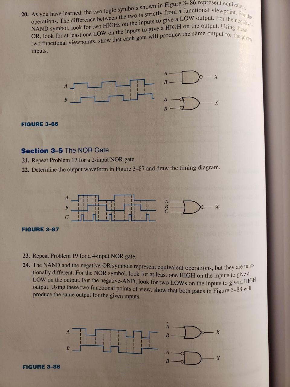
20. As you have learned, the two logic symbols shown in Figure 3-86 represent equivalent operations. The difference between the two is strictly from a functional viewpoint. For the NAND symbol, look for two HIGHs on the inputs to give a LOW output. For the negative. OR, look for at least one LOW on the inputs to give a HIGH on the output. Using thicse two functional viewpoints, show that each gate will produce the same output for the given inputs. FIGURE 3-86 Section 3-5 The NOR Gate 21. Repeat Problem 17 for a 2-input NOR gate. 22. Determine the output waveform in Figure 3-87 and draw the timing diagram. FIGURE 3-8. 23. Repeat Problem 19 for a 4-input NOR gate. 24. The NAND and the negative-OR symbols represent equivalent operations, but they are functionally different. For the NOR symbol, look for at least one HIGH on the inputs to give a LOW on the output. For the negative-AND, look for two LOWs on the inputs to give a HIGH output. Using these two functional points of view, show that both gates in Figure 3-88 will produce the same output for the given inputs. FIGURE 3
Step by Step Solution
There are 3 Steps involved in it

Get step-by-step solutions from verified subject matter experts