

Question: PLEASE answer part A and part C ONLY. STREAM 1 Fs1, Ts1, CAS1 STREAM 2 Fs2, Tsz, CBS2 STREAM 3 STREAM 4 F54, 7:4, CR54
PLEASE answer part A and part C ONLY.
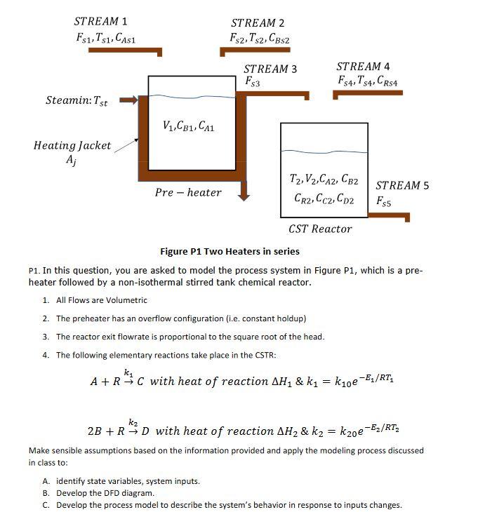
STREAM 1 Fs1, Ts1, CAS1 STREAM 2 Fs2, Tsz, CBS2 STREAM 3 STREAM 4 F54, 7:4, CR54 F53 Steamin:Tst V1,CB1, C11 Heating Jacket A; Pre-heater T2, V2,CA2, CB2 CR2, Cc2, CD2 STREAM 5 F35 CST Reactor Figure P1 Two Heaters in series P1. In this question, you are asked to model the process system in Figure P1, which is a pre- heater followed by a non-isothermal stirred tank chemical reactor. 1. All Flows are Volumetric 2. The preheater has an overflow configuration (i.e. constant holdup) 3. The reactor exit flowrate is proportional to the square root of the head. 4. The following elementary reactions take place in the CSTR: ke A+R* C with heat of reaction AH & k = kloe-Es/RT, kz 2B+R 3D with heat of reaction AH2 & k2 = k20e -Ez/RT> Make sensible assumptions based on the information provided and apply the modeling process discussed in class to: A. identify state variables, system inputs. B. Develop the DFD diagram. C. Develop the process model to describe the system's behavior in response to inputs changes. STREAM 1 Fs1, Ts1, CAS1 STREAM 2 Fs2, Tsz, CBS2 STREAM 3 STREAM 4 F54, 7:4, CR54 F53 Steamin:Tst V1,CB1, C11 Heating Jacket A; Pre-heater T2, V2,CA2, CB2 CR2, Cc2, CD2 STREAM 5 F35 CST Reactor Figure P1 Two Heaters in series P1. In this question, you are asked to model the process system in Figure P1, which is a pre- heater followed by a non-isothermal stirred tank chemical reactor. 1. All Flows are Volumetric 2. The preheater has an overflow configuration (i.e. constant holdup) 3. The reactor exit flowrate is proportional to the square root of the head. 4. The following elementary reactions take place in the CSTR: ke A+R* C with heat of reaction AH & k = kloe-Es/RT, kz 2B+R 3D with heat of reaction AH2 & k2 = k20e -Ez/RT> Make sensible assumptions based on the information provided and apply the modeling process discussed in class to: A. identify state variables, system inputs. B. Develop the DFD diagram. C. Develop the process model to describe the system's behavior in response to inputs changes
Step by Step Solution
There are 3 Steps involved in it

Get step-by-step solutions from verified subject matter experts