

Question: Please Answer Part A Q.5: Consider a two-tank system as shown in Figure 1. Define the states to be liquid level in each tank (denoted
Please Answer Part A
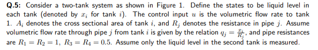
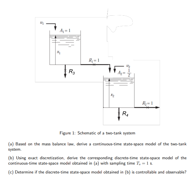
Q.5: Consider a two-tank system as shown in Figure 1. Define the states to be liquid level in each tank (denoted by I; for tank i). The control input u is the volumetric flow rate to tank 1. A; denotes the cross sectional area of tank i, and R; denotes the resistance in pipe j. Assume volumetric flow rate through pipe j from tank i is given by the relation q; = and pipe resistances are R1 = R2 = 1, R3 = Rs = 0.5. Assume only the liquid level in the second tank is measured. 11 u A = 1 X1 Ri= 1 2 R3 A2 = 2 X2 R = 1 RA Figure 1: Schematic of a two-tank system (a) Based on the mass balance law, derive a continuous-time state-space model of the two-tank system. (b) Using exact discretization, derive the corresponding discrete-time state-space model of the continuous-time state-space model obtained in (a) with sampling time Tg = 1 s. (c) Determine if the discrete-time state-space model obtained in (b) is controllable and observable
Step by Step Solution
There are 3 Steps involved in it

Get step-by-step solutions from verified subject matter experts