

Question: Please do all parts a) Completed ASM chart shown in Figure 1 by specifying the missing HLO output patterns, LLTtimer values in the appropriate states
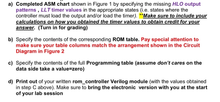
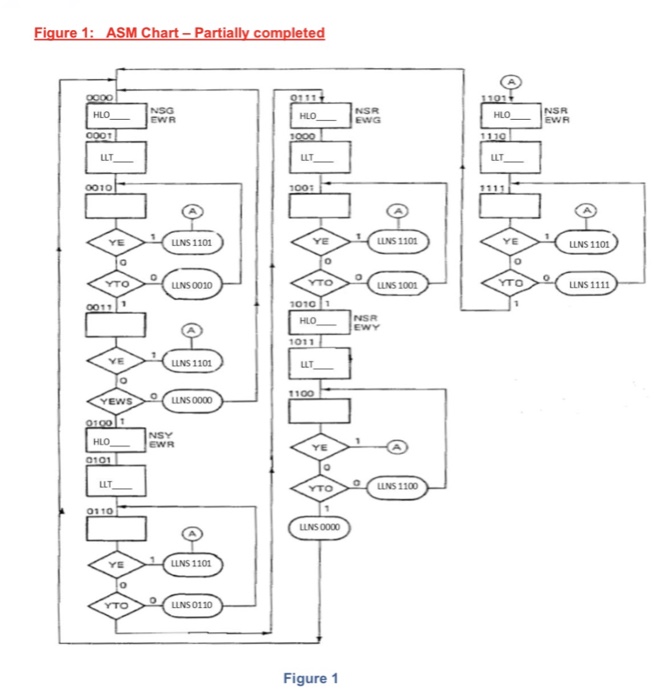
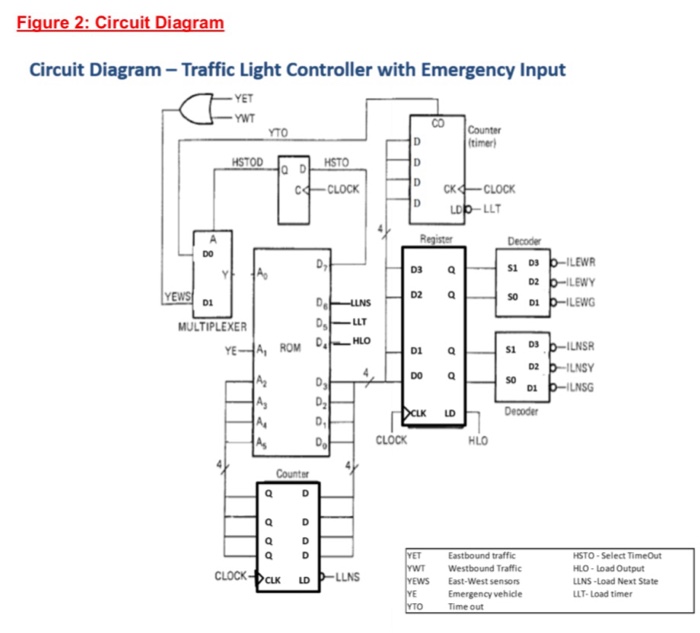
a) Completed ASM chart shown in Figure 1 by specifying the missing HLO output patterns, LLTtimer values in the appropriate states (i e. states where the controller must load the output and/or load the timer Make sure to include your calculations on how you obtained the timer values to obtain credit for your answer. Turn in for grading) b) Specify the contents of the corresponding ROM table. Pay special attention to make sure your table columns match the arrangement shown in the Circuit Diagram in Figure 2 c) Specify the contents of the full Programming table (assume don't cares on the data side take a value zero) d) Print out of your written rom controller verilog module (with the values obtained in step C above). Make sure to bring the electronic version with you at the start of your lab session
Step by Step Solution
There are 3 Steps involved in it

Get step-by-step solutions from verified subject matter experts