

Question: PLEASE DO BY HAND!!!! Examples that are referenced in the question are also included. Please make answer similar to the examples provided. Thanks!! Exercise 4.
PLEASE DO BY HAND!!!! Examples that are referenced in the question are also included. Please make answer similar to the examples provided. Thanks!! 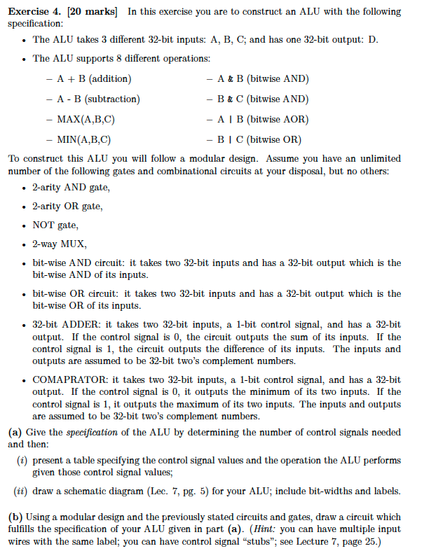
![4. [20 marks] In this exercise you are to construct an ALU](https://dsd5zvtm8ll6.cloudfront.net/si.experts.images/questions/2024/09/66f5242dd716f_61366f5242d2b8ad.jpg)
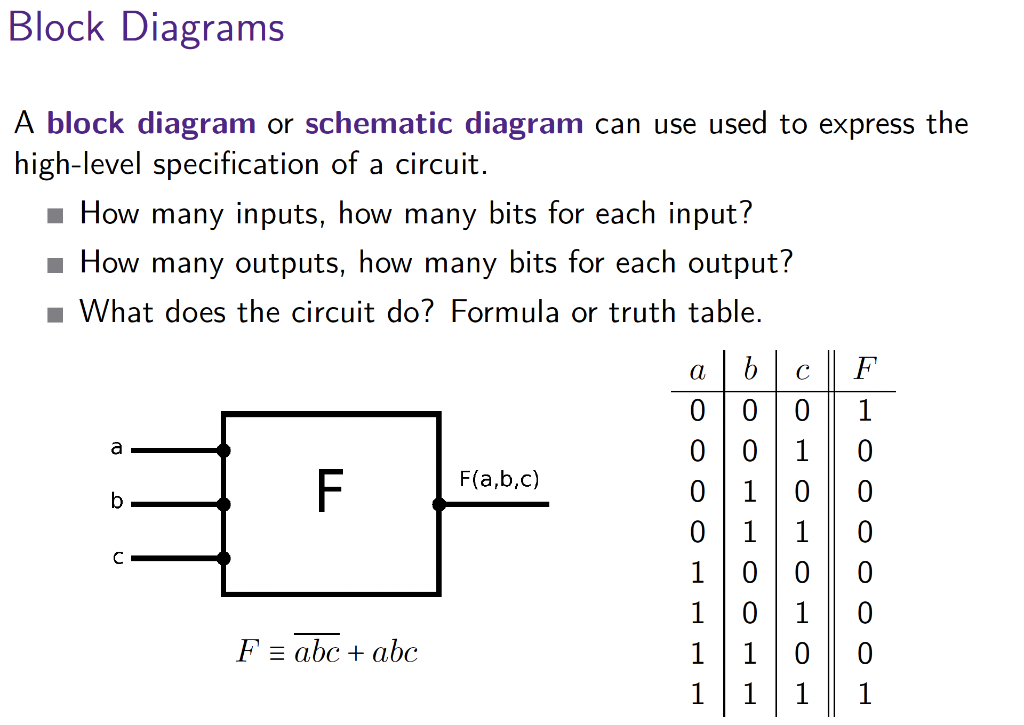
Exercise 4. [20 marks] In this exercise you are to construct an ALU with the following specification: - The ALU takes 3 different 32-bit inputs: A, B, C; and has one 32-bit output: D. - The ALU supports 8 different operations: A+B(addition)AB(subtraction)MAX(A,B,C)MIN(A,B,C)A&B(bitwiseAND)B&C(bitwiseAND)AB(bitwiseAOR)BC(bitwiseOR) To construct this ALU you will follow a modular design. Assume you have an unlimited number of the following gates and combinational circuits at your disposal, but no others: - 2-arity AND gate, - 2-arity OR gate, - NOT gate, - 2-way MUX, - bit-wise AND circuit: it takes two 32-bit inputs and has a 32-bit output which is the bit-wise AND of its inputs. - bit-wise OR circuit: it takes two 32-bit inputs and has a 32-bit output which is the bit-wise OR of its inputs. - 32-bit ADDER: it takes two 32-bit inputs, a 1-bit control signal, and has a 32-bit output. If the control signal is 0 , the circuit outputs the sum of its inputs. If the control signal is 1 , the circuit outputs the difference of its inputs. The inputs and outputs are assumed to be 32-bit two's complement numbers. - COMAPRATOR: it takes two 32-bit inputs, a 1-bit control signal, and has a 32-bit output. If the control signal is 0 , it outputs the minimum of its two inputs. If the control signal is 1, it outputs the maximum of its two inputs. The inputs and outputs are assumed to be 32-bit two's complement numbers. (a) Give the specification of the ALU by determining the number of control signals needed and then: (i) present a table specifying the control signal values and the operation the ALU performs given those control signal values; (ii) draw a schematic diagram (Lec. 7, pg. 5) for your ALU; include bit-widths and labels. (b) Using a modular design and the previously stated circuits and gates, draw a circuit which fulfills the specification of your ALU given in part (a). (Hint: you can have multiple input wires with the same label; you can have control signal "stubs"; see Lecture 7, page 25.) A block diagram or schematic diagram can use used to express the high-level specification of a circuit. - How many inputs, how many bits for each input? How many outputs, how many bits for each output? What does the circuit do? Formula or truth table. Simple ALU Circuit
Step by Step Solution
There are 3 Steps involved in it

Get step-by-step solutions from verified subject matter experts