

Question: PLEASE DO NOT COPY AND COMPLETE ALL PARTS FOR POSITIVE FEEDBACK! UPVOTE The structural part of a setup to measure net belt tensions in pulleys
PLEASE DO NOT COPY AND COMPLETE ALL PARTS FOR POSITIVE FEEDBACK! UPVOTE
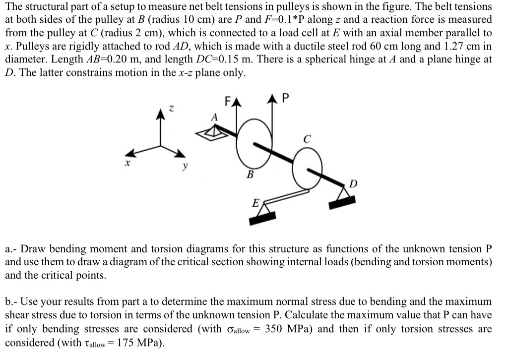
The structural part of a setup to measure net belt tensions in pulleys is shown in the figure. The belt tensions
at both sides of the pulley at radius cm are and along and a reaction force is measured
from the pulley at radius cm which is connected to a load cell at with an axial member parallel to
Pulleys are rigidly attached to rod which is made with a ductile steel rod cm long and cm in
diameter. Length and length There is a spherical hinge at A and a plane hinge at
The latter constrains motion in the plane only.
a Draw bending moment and torsion diagrams for this structure as functions of the unknown tension P
and use them to draw a diagram of the critical section showing internal loads bending and torsion moments
and the critical points.
b Use your results from part a to determine the maximum normal stress due to bending and the maximum
shear stress due to torsion in terms of the unknown tension P Calculate the maximum value that P can have
if only bending stresses are considered with MPa and then if only torsion stresses are
considered with MPa
The structural part of a setup to measure net belt tensions in pulleys is shown in the figure. The belt tensions
at both sides of the pulley at radius cm are and along and a reaction force is measured
from the pulley at radius cm which is connected to a load cell at with an axial member parallel to
Pulleys are rigidly attached to rod which is made with a ductile steel rod cm long and cm in
diameter. Length and length There is a spherical hinge at A and a plane hinge at
The latter constrains motion in the z plane only.
a Draw bending moment and torsion diagrams for this structure as functions of the unknown tension P
and use them to draw a diagram of the critical section showing internal loads bending and torsion moments
and the critical points.
b Use your results from part a to determine the maximum normal stress due to bending and the maximum
shear stress due to torsion in terms of the unknown tension P Calculate the maximum value that P can have
if only bending stresses are considered with MPa and then if only torsion stresses are
considered with MPa
Step by Step Solution
There are 3 Steps involved in it
1 Expert Approved Answer
Step: 1 Unlock

Question Has Been Solved by an Expert!
Get step-by-step solutions from verified subject matter experts
Step: 2 Unlock
Step: 3 Unlock