

Question: Please do question 2, 3, and 4 H(s) = A high Q bandpass filter is shown in the Figure (Hint: Several of the nodes are
Please do question 2, 3, and 4
H(s) =
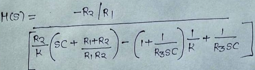
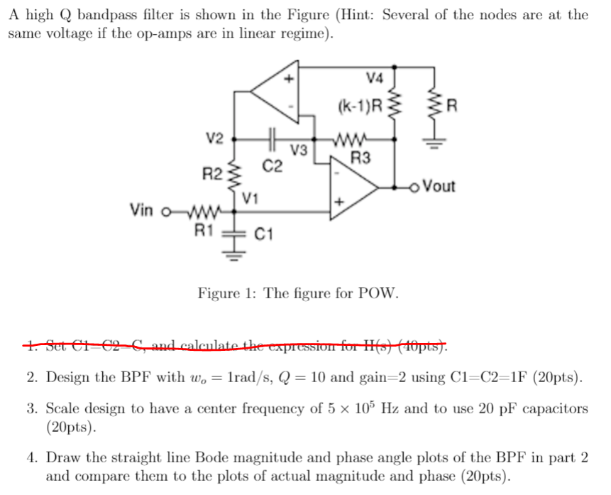
A high Q bandpass filter is shown in the Figure (Hint: Several of the nodes are at the same voltage if the op-amps are in linear regime). 14 (k-1) R V2 HE V3 R3 R2 C2 Vout V1 + Vinow R 1 C1 Figure 1: The figure for POW. 1. Set 61-62-6_and calculate the expression for H1 (10ptst. 7. and 2. Design the BPF with w, = Trad/s, Q = 10 and gain=2 using C1=C2=1F (20pts). 3. Scale design to have a center frequency of 5 x 10⁵ Hz and to use 20 pF capacitors (20pts). 4. Draw the straight line Bode magnitude and phase angle plots of the BPF in part 2 and compare them to the plots of actual magnitude and phase (20pts). M(S) - -R2/RI + It + R2 K SC + R1+R2 RIRA . 1 R3SC R K R3SC
Step by Step Solution
There are 3 Steps involved in it

Get step-by-step solutions from verified subject matter experts