

Question: Please explain - TIA A BEQ instruction at memory address 644 and encoded in hexadecimal as FCA286E3 is being executed. Given that registers x0 to
Please explain - TIA
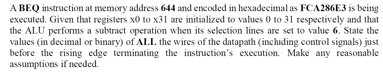
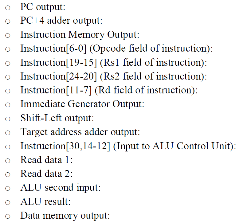
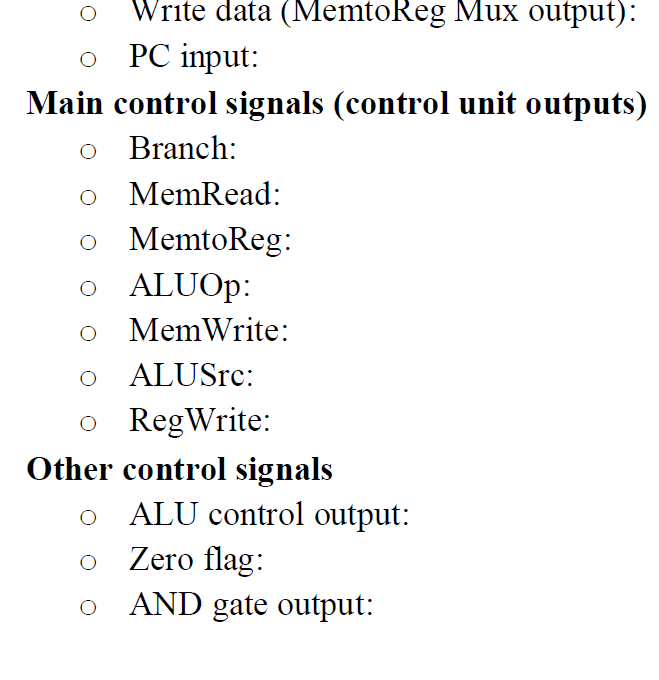
A BEQ instruction at memory address 644 and encoded in hexadecimal as FCA286E3 is being executed. Given that registers x0 to x31 are initialized to values 0 to 31 respectively and that the ALU performs a subtract operation when its selection lines are set to value 6. State the values (in decimal or binary) of ALL the wires of the datapath (including control signals) just before the rising edge terminating the instruction's execution. Make any reasonable assumptions if needed. O O PC output: PC+4 adder output: O Instruction Memory Output: Instruction[6-0] (Opcode field of instruction): Instruction[19-15] (Rs1 field of instruction): Instruction[24-20] (Rs2 field of instruction): o Instruction[11-7] (Rd field of instruction): Immediate Generator Output: Shift-Left output: o Target address adder output: 0 Instruction[30,14-12] (Input to ALU Control Unit): Read data 1: O Read data 2: ALU second input: ALU result: Data memory output: O O O Write data (MemtoReg Mux output): 0 PC input: Main control signals (control unit outputs) O Branch: o MemRead: MemtoReg: 0 ALUOP: 0 MemWrite: O ALUSrc: 0 RegWrite: Other control signals ALU control output: o Zero flag: O AND gate output: A BEQ instruction at memory address 644 and encoded in hexadecimal as FCA286E3 is being executed. Given that registers x0 to x31 are initialized to values 0 to 31 respectively and that the ALU performs a subtract operation when its selection lines are set to value 6. State the values (in decimal or binary) of ALL the wires of the datapath (including control signals) just before the rising edge terminating the instruction's execution. Make any reasonable assumptions if needed. O O PC output: PC+4 adder output: O Instruction Memory Output: Instruction[6-0] (Opcode field of instruction): Instruction[19-15] (Rs1 field of instruction): Instruction[24-20] (Rs2 field of instruction): o Instruction[11-7] (Rd field of instruction): Immediate Generator Output: Shift-Left output: o Target address adder output: 0 Instruction[30,14-12] (Input to ALU Control Unit): Read data 1: O Read data 2: ALU second input: ALU result: Data memory output: O O O Write data (MemtoReg Mux output): 0 PC input: Main control signals (control unit outputs) O Branch: o MemRead: MemtoReg: 0 ALUOP: 0 MemWrite: O ALUSrc: 0 RegWrite: Other control signals ALU control output: o Zero flag: O AND gate output
Step by Step Solution
There are 3 Steps involved in it

Get step-by-step solutions from verified subject matter experts