

Question: Please Follow howework document procedure. The Diagram should be a kinematic sketch. The Solution should briefly explain how you constructed it in SolidWorks and tracked
Please Follow howework document procedure. The Diagram should be a kinematic sketch. The Solution should briefly
explain how you constructed it in SolidWorks and tracked the required angles and then
ending in a reference to the SolidWorks printout that is probably on the next page. Also
included is any calculations of course. The Conclusion should discuss interesting
observations about the process that you encountered or noticed.
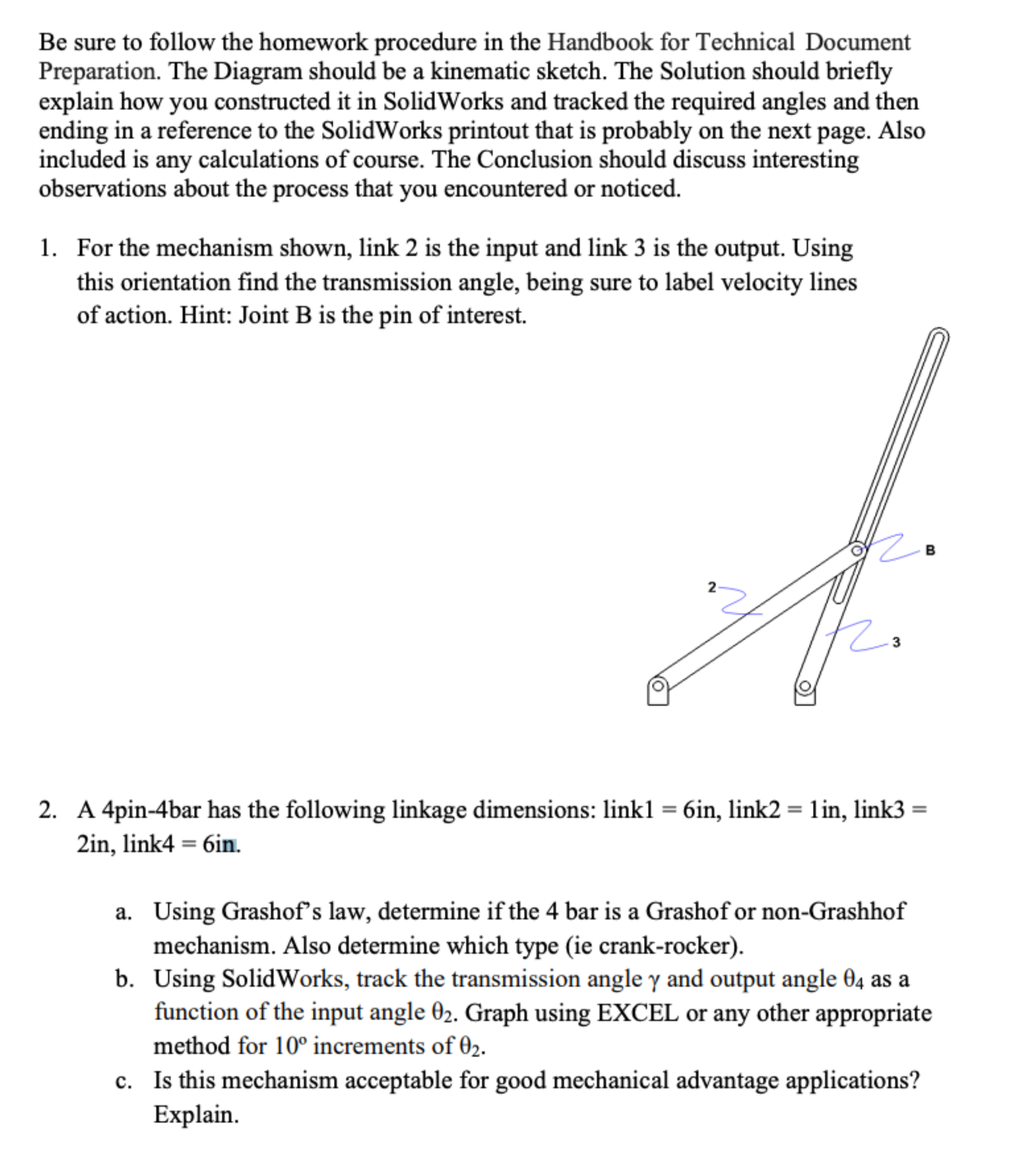
For the mechanism shown, link is the input and link is the output. Using
this orientation find the transmission angle, being sure to label velocity lines
of action. Hint: Joint B is the pin of interest.
A pinbar has the following linkage dimensions: link link link
in link
a Using Grashof's law, determine if the bar is a Grashof or nonGrashhof
mechanism. Also determine which type ie crankrocker
b Using SolidWorks, track the transmission angle and output angle as a
function of the input angle Graph using EXCEL or any other appropriate
method for increments of
c Is this mechanism acceptable for good mechanical advantage applications?
Explain.Introductory Homework
Due Thursday
Be sure to follow the homework procedure in the Handbook for Technical Document
Preparation. The Diagram should be a kinematic sketch. The Solution should briefly
explain how you constructed it in SolidWorks and tracked the required angles and then
ending in a reference to the SolidWorks printout that is probably on the next page. Also
included is any calculations of course. The Conclusion should discuss interesting
observations about the process that you encountered or noticed.
For the mechanism shown, link is the input and link is the output. Using
this orientation find the transmission angle, being sure to label velocity lines
of action. Hint: Joint B is the pin of interest.
A pinbar has the following linkage dimensions: linkin linkin link
in linkin
a Using Grashofs law, determine if the bar is a Grashof or nonGrashhof
mechanism. Also determine which type ie crankrocker
b Using SolidWorks, track the transmission angle gamma and output angle theta as a
function of the input angle theta Graph using EXCEL or any other appropriate
method for increments of theta
c Is this mechanism acceptable for good mechanical advantage applications?
Explain.
For the given figure:
a Using Kutzbachs criterion, determine the mobility of the bar shaper
mechanism. Also identify the bars within this mechanism.
b Using SolidWorks, determine the range of the input for which the mechanism
is valid, taking into account geometric limitations and requirements for
acceptable transmission angles. Link is the input and link is the final
output.
c For the input range found in b find the working travel of the sliding ram,
link
Dimensions in inches include:
Other arm of input link called a bell crank
Using SolidWorks, design a pin bar quick return mechanism with an
advancetoreturn ratio Q The rocker is to have a length of inches and
oscillate through a total angle range of
Step by Step Solution
There are 3 Steps involved in it
1 Expert Approved Answer
Step: 1 Unlock

Question Has Been Solved by an Expert!
Get step-by-step solutions from verified subject matter experts
Step: 2 Unlock
Step: 3 Unlock