

Question: Please help, I am having a very hard time with this. Here is the example from the book: Filter L Lowest Frequency Signal Picked-up signal
Please help, I am having a very hard time with this.
Here is the example from the book:
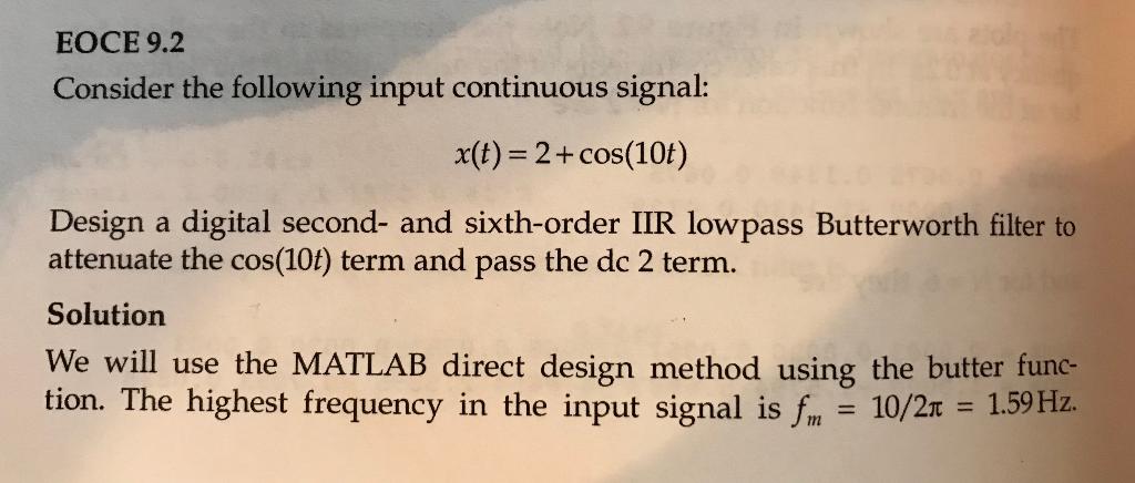
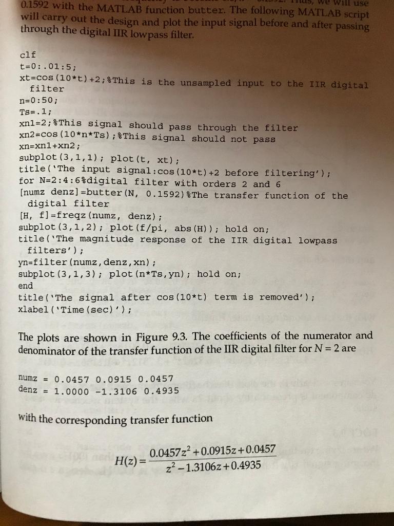
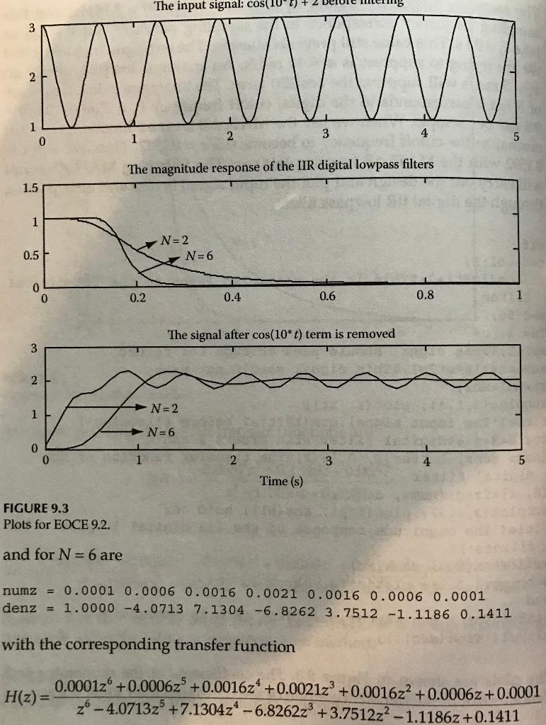
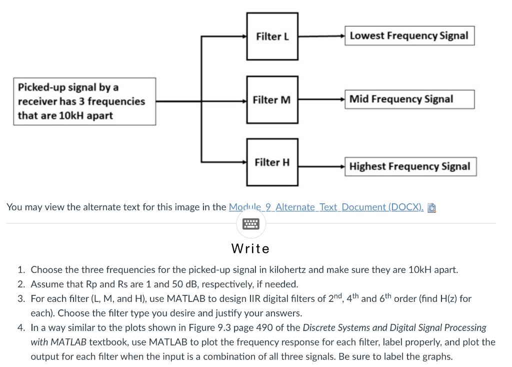
Filter L Lowest Frequency Signal Picked-up signal by a receiver has 3 frequencies that are 10kH apart Filter M Mid Frequency Signal Filter H Highest Frequency Signal You may view the alternate text for this image in the Module 9 Alternate Text Document (DOCX). Write 1. Choose the three frequencies for the picked-up signal in kilohertz and make sure they are 10kH apart. 2. Assume that Rp and Rs are 1 and 50 dB, respectively, if needed. 3. For each filter (L, M, and H), use MATLAB to design IIR digital filters of 2nd, 4th and 6th order (find H(z) for each). Choose the filter type you desire and justify your answers. 4. In a way similar to the plots shown in Figure 9.3 page 490 of the Discrete Systems and Digital Signal Processing with MATLAB textbook, use MATLAB to plot the frequency response for each filter, label properly, and plot the output for each filter when the input is a combination of all three signals. Be sure to label the graphs. EOCE 9.2 Consider the following input continuous signal: x(t)= 2+ cos(10t) Design a digital second- and sixth-order IIR lowpass Butterworth filter to attenuate the cos(10t) term and pass the dc 2 term. Solution We will use the MATLAB direct design method using the butter func- tion. The highest frequency in the input signal is fm 10/21 = 1.59 Hz. we will use 0.1592 with the MATLAB function butter. The following MATLAB script will carry out the design and plot the input signal before and after passing through the digital IIR low pass filter. clf t=0:.01:5; xt=cos (10*t) +2; 8 This is the unsampled input to the IIR digital filter n=0:50; Ts=.1; xn1=2; $This signal should pass through the filter xn2=cOS (10*n*Ts); % This signal should not pass xn=xn1+xn2; subplot (3,1,1); plot(t, xt); title ('The input signal:cos (10*t) +2 before filtering') ; for N=2:4:6%digital filter with orders 2 and 6 [numz denz] =butter (N, 0.1592) The transfer function of the digital filter [H, f]=freqz (numz, denz); subplot (3,1,2); plot (f/pi, abs (H)); hold on; title('The magnitude response of the IIR digital lowpass filters'); yn=filter (numz, denz,xn); subplot (3,1,3); plot (n*Ts, yn); hold on; end title('The signal after cos(10*t) term is removed'); xlabel ('Time (sec)'); The plots are shown in Figure 9.3. The coefficients of the numerator and denominator of the transfer function of the IIR digital filter for N = 2 are numz = 0.0457 0.0915 0.0457 denz = 1.0000 -1.3106 0.4935 with the corresponding transfer function 0.0457z2 +0.09152 +0.0457 H(z)= z? - 1.31062 +0.4935 The input signal: cos(IU W V 1 0 3 2 4 1 5 The magnitude response of the IIR digital lowpass filters 1.5 1 N=2 N=6 0.5 0 0 0.2 0.4 0.6 0.8 1 The signal after cos(10* t) term is removed 3 2 N=2 1 N=6 0 0 1 2 3 5 Time (s) FIGURE 9.3 Plots for EOCE 9.2. and for N = 6 are numz = 0.0001 0.0006 0.0016 0.0021 0.0016 0.0006 0.0001 denz = 1.0000 -4.0713 7.1304 -6.8262 3.7512 -1.1186 0.1411 with the corresponding transfer function 0.000126 +0.00062 +0.001624 +0.002123 +0.001622 +0.00062 +0.0001 H(z)= -4.0713z +7.1304z - 6.82622 +3.751222 - 1.11862 +0.1411 Filter L Lowest Frequency Signal Picked-up signal by a receiver has 3 frequencies that are 10kH apart Filter M Mid Frequency Signal Filter H Highest Frequency Signal You may view the alternate text for this image in the Module 9 Alternate Text Document (DOCX). Write 1. Choose the three frequencies for the picked-up signal in kilohertz and make sure they are 10kH apart. 2. Assume that Rp and Rs are 1 and 50 dB, respectively, if needed. 3. For each filter (L, M, and H), use MATLAB to design IIR digital filters of 2nd, 4th and 6th order (find H(z) for each). Choose the filter type you desire and justify your answers. 4. In a way similar to the plots shown in Figure 9.3 page 490 of the Discrete Systems and Digital Signal Processing with MATLAB textbook, use MATLAB to plot the frequency response for each filter, label properly, and plot the output for each filter when the input is a combination of all three signals. Be sure to label the graphs. EOCE 9.2 Consider the following input continuous signal: x(t)= 2+ cos(10t) Design a digital second- and sixth-order IIR lowpass Butterworth filter to attenuate the cos(10t) term and pass the dc 2 term. Solution We will use the MATLAB direct design method using the butter func- tion. The highest frequency in the input signal is fm 10/21 = 1.59 Hz. we will use 0.1592 with the MATLAB function butter. The following MATLAB script will carry out the design and plot the input signal before and after passing through the digital IIR low pass filter. clf t=0:.01:5; xt=cos (10*t) +2; 8 This is the unsampled input to the IIR digital filter n=0:50; Ts=.1; xn1=2; $This signal should pass through the filter xn2=cOS (10*n*Ts); % This signal should not pass xn=xn1+xn2; subplot (3,1,1); plot(t, xt); title ('The input signal:cos (10*t) +2 before filtering') ; for N=2:4:6%digital filter with orders 2 and 6 [numz denz] =butter (N, 0.1592) The transfer function of the digital filter [H, f]=freqz (numz, denz); subplot (3,1,2); plot (f/pi, abs (H)); hold on; title('The magnitude response of the IIR digital lowpass filters'); yn=filter (numz, denz,xn); subplot (3,1,3); plot (n*Ts, yn); hold on; end title('The signal after cos(10*t) term is removed'); xlabel ('Time (sec)'); The plots are shown in Figure 9.3. The coefficients of the numerator and denominator of the transfer function of the IIR digital filter for N = 2 are numz = 0.0457 0.0915 0.0457 denz = 1.0000 -1.3106 0.4935 with the corresponding transfer function 0.0457z2 +0.09152 +0.0457 H(z)= z? - 1.31062 +0.4935 The input signal: cos(IU W V 1 0 3 2 4 1 5 The magnitude response of the IIR digital lowpass filters 1.5 1 N=2 N=6 0.5 0 0 0.2 0.4 0.6 0.8 1 The signal after cos(10* t) term is removed 3 2 N=2 1 N=6 0 0 1 2 3 5 Time (s) FIGURE 9.3 Plots for EOCE 9.2. and for N = 6 are numz = 0.0001 0.0006 0.0016 0.0021 0.0016 0.0006 0.0001 denz = 1.0000 -4.0713 7.1304 -6.8262 3.7512 -1.1186 0.1411 with the corresponding transfer function 0.000126 +0.00062 +0.001624 +0.002123 +0.001622 +0.00062 +0.0001 H(z)= -4.0713z +7.1304z - 6.82622 +3.751222 - 1.11862 +0.1411
Step by Step Solution
There are 3 Steps involved in it

Get step-by-step solutions from verified subject matter experts