

Question: Please help, I need to see how this is done and then written in VHDL so that I can understand how to do the rest
Please help, I need to see how this is done and then written in VHDL so that I can understand how to do the rest of the assignments moving forward.
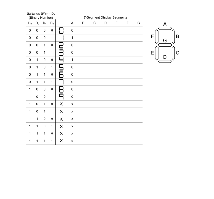
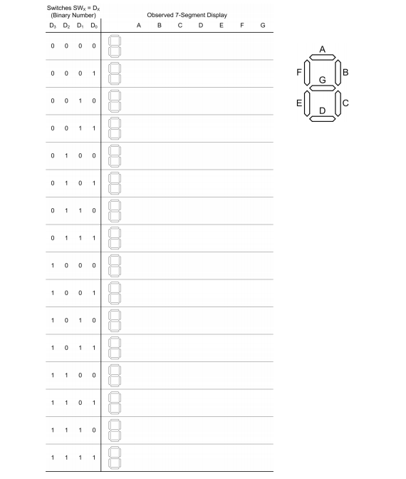
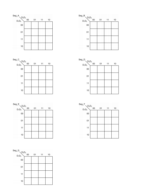
Objectives Use Karnaugh maps with don't cares to minimize a circuit Implement a minimized digital circuit to control a 7-segment display digit Verify correct operation using perfect induction (exhaustive testing) on the board Functional Specification In this lab you will implement and test a circuit that displays a decimal digit (0-9) that corresponds to the binary number entered using four switches. Binary inputs with decimal values of 10 or higher are invalid. 1. 1/0 a. Switches SW3, SW2, SWI and SWO, inputs, STD_LOGIC b. 7-segment display SEGMENT_A, SEGMENT_B, ..., SEGMENT_G, outputs, STD LOGIC c. 7-segment display ANODE3, ANODE2, ANODEI, ANODEO, outputs, STD_LOGIC 2. Operation a. The rightmost digit of the 7-segment display shows the decimal digit corresponding to the binary number entered using the switches. Only inputs of 010 (00002) through 910 (10012) are valid, anything above that is considered invalid input. The segment pattern is indicated in the 7- Segment Digit Design Worksheet posted on Canvas. b. The other three digits are blank (off). Discussion In this lab you will implement a digital circuit to display a decimal digit based on the position of four switches. You will begin by making a truth table that includes an output for each segment in the digit. Inputs of 1010 (10102) and above are invalid, so you will use don't cares for the corresponding outputs. You will use K-maps to find the minimal Boolean equations for each segment and draw circuits that implement each segment. You will then use VHDL to describe your circuits, then synthesize and configure your Basys-3 board. In the previous lab, you displayed a hexadecimal digit, and implemented it using canonical SOP form. In this lab you will use don't cares because you are not implementing hexadecimal digits A-F. You will also minimize your circuit using K-maps, so your resulting implementation should use far fewer gates than your previous implementation. Lab Exercises 1) Print the 7-Segment Digit Design Worksheet posted on Canvas (Lab05_7SegmentDesign Worksheet.pdf). a. Complete the truth table for the 7-segment display segments, using don't cares for inputs 1010 through 1510. This is partially done for you, and should be the same as your truth table from the last lab (except for the don't cares). b. Put the values in your truth table into the K-maps for each segment. Values for segment A are put into a K-map for you. c. Find the minimized Boolean function for each segment. d. Draw a circuit that implements each segment. 7-Segment Display Segments B C D E F G Switches SWX = DX (Binary Number) D, D2 D.D. A 0 0 0 0 0 0 0 0 0 1 0 0 1 0 2 0 0 1 1 3 0 1 0 0 4 0 1 0 115 0 1 1 0 0 1 1 117 1 0 0 0 8 1 0 0 19 0 1 0 1 0 X X 1 0 1 1 x x 1 1 0 0 1 x x 1 1 0 1 x x 1 1 1 0 * * 1 1 1 1 X X Switches SW -D (Binary Number) D, D D. D A Observed 7-Segment Display B C D E F G 0 0 0 0 0 0 0 1 0 0 1 0 0 0 1 1 0 1 0 0 0 1 0 1 0 1 1 0 0 1 1 1 1 0 0 0 1 0 0 1 COOOOOOOOOOOOOOOOOOOO 1 0 1 0 1 0 1 1 1 1 0 0 1 1 0 1 1 1 1 0 Seg. A DD Seg DD2 D.D. 00 01 11 10 00011110 01 11 S DP Seg D.DE 00 01 01 11 10 00 01 11 10 Seg Seg. DO 01 DD D.D. 00 01 01 11 10 00 01 11 10 Seg G D.D D.D. 0001 11 10 Objectives Use Karnaugh maps with don't cares to minimize a circuit Implement a minimized digital circuit to control a 7-segment display digit Verify correct operation using perfect induction (exhaustive testing) on the board Functional Specification In this lab you will implement and test a circuit that displays a decimal digit (0-9) that corresponds to the binary number entered using four switches. Binary inputs with decimal values of 10 or higher are invalid. 1. 1/0 a. Switches SW3, SW2, SWI and SWO, inputs, STD_LOGIC b. 7-segment display SEGMENT_A, SEGMENT_B, ..., SEGMENT_G, outputs, STD LOGIC c. 7-segment display ANODE3, ANODE2, ANODEI, ANODEO, outputs, STD_LOGIC 2. Operation a. The rightmost digit of the 7-segment display shows the decimal digit corresponding to the binary number entered using the switches. Only inputs of 010 (00002) through 910 (10012) are valid, anything above that is considered invalid input. The segment pattern is indicated in the 7- Segment Digit Design Worksheet posted on Canvas. b. The other three digits are blank (off). Discussion In this lab you will implement a digital circuit to display a decimal digit based on the position of four switches. You will begin by making a truth table that includes an output for each segment in the digit. Inputs of 1010 (10102) and above are invalid, so you will use don't cares for the corresponding outputs. You will use K-maps to find the minimal Boolean equations for each segment and draw circuits that implement each segment. You will then use VHDL to describe your circuits, then synthesize and configure your Basys-3 board. In the previous lab, you displayed a hexadecimal digit, and implemented it using canonical SOP form. In this lab you will use don't cares because you are not implementing hexadecimal digits A-F. You will also minimize your circuit using K-maps, so your resulting implementation should use far fewer gates than your previous implementation. Lab Exercises 1) Print the 7-Segment Digit Design Worksheet posted on Canvas (Lab05_7SegmentDesign Worksheet.pdf). a. Complete the truth table for the 7-segment display segments, using don't cares for inputs 1010 through 1510. This is partially done for you, and should be the same as your truth table from the last lab (except for the don't cares). b. Put the values in your truth table into the K-maps for each segment. Values for segment A are put into a K-map for you. c. Find the minimized Boolean function for each segment. d. Draw a circuit that implements each segment. 7-Segment Display Segments B C D E F G Switches SWX = DX (Binary Number) D, D2 D.D. A 0 0 0 0 0 0 0 0 0 1 0 0 1 0 2 0 0 1 1 3 0 1 0 0 4 0 1 0 115 0 1 1 0 0 1 1 117 1 0 0 0 8 1 0 0 19 0 1 0 1 0 X X 1 0 1 1 x x 1 1 0 0 1 x x 1 1 0 1 x x 1 1 1 0 * * 1 1 1 1 X X Switches SW -D (Binary Number) D, D D. D A Observed 7-Segment Display B C D E F G 0 0 0 0 0 0 0 1 0 0 1 0 0 0 1 1 0 1 0 0 0 1 0 1 0 1 1 0 0 1 1 1 1 0 0 0 1 0 0 1 COOOOOOOOOOOOOOOOOOOO 1 0 1 0 1 0 1 1 1 1 0 0 1 1 0 1 1 1 1 0 Seg. A DD Seg DD2 D.D. 00 01 11 10 00011110 01 11 S DP Seg D.DE 00 01 01 11 10 00 01 11 10 Seg Seg. DO 01 DD D.D. 00 01 01 11 10 00 01 11 10 Seg G D.D D.D. 0001 11 10
Step by Step Solution
There are 3 Steps involved in it

Get step-by-step solutions from verified subject matter experts