

Question: Please Help Me With this all please 8- The block diagram shown in the following figure represents the hardware that implements the following microoperations (b(a'+b+c)(a'+b'+c).:
Please Help Me With this all please
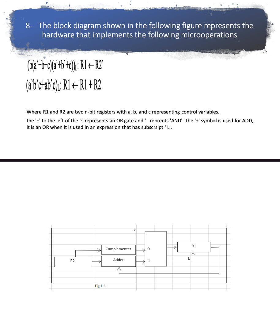
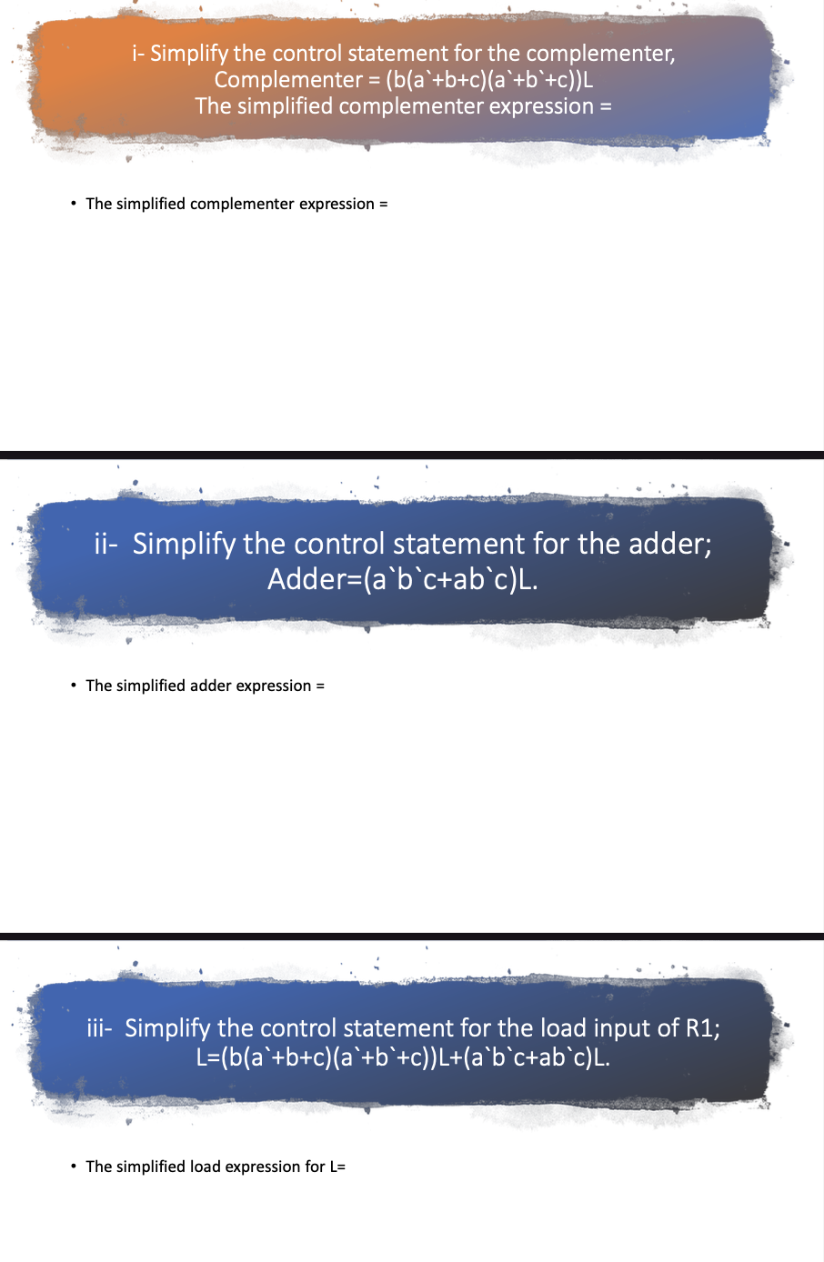
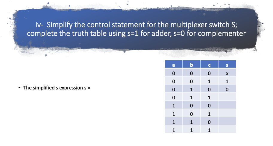
8- The block diagram shown in the following figure represents the hardware that implements the following microoperations (b(a'+b+c)(a'+b'+c).: R1 + R2 (a'b'ctabc): R1+R1+R2 Where R1 and R2 are two n-bit registers with a, b, and c representing control variables. the '+' to the left of the ':' represents an OR gate and '' reprents 'AND'. The 't' symbol is used for ADD, it is an OR when it is used in an expression that has subscript 'L'. R1 Complementer 0 R2 Adder Fig. 1.1 i- Simplify the control statement for the complementer, Complementer = (b(a +b+c)(a +b+c))L The simplified complementer expression = The simplified complementer expression = ii- Simplify the control statement for the adder; Adder=(a`bc+ab`c)L. The simplified adder expression = iii- Simplify the control statement for the load input of R1; L=(b(a +b+c)(a +b +c))L+(a bc+abc)L. The simplified load expression for L= iv- Simplify the control statement for the multiplexer switch S; complete the truth table using s=1 for adder, s=0 for complementer a b S 0 0 0 0 0 1 0 1 The simplified s expression s = 1 0 O 1 1 0 1 0 0 0 1 1 1 1 0 1 1 1
Step by Step Solution
There are 3 Steps involved in it

Get step-by-step solutions from verified subject matter experts