

Question: Please help me with this! I need this ASAP.. Thank you so much. Instructions: you will need detailed logical network diagram . A detailed network
Please help me with this! I need this ASAP.. Thank you so much.
Instructions: you will need detailed logical network diagram. A detailed network diagram will include, but is not limited to, device descriptions, device manufacturer, device model, physical addresses (MAC), Internet protocol (IP) addresses, building and room information, connection medium(s) (Ethernet, fiber, serial), connection ports, operating system, and logical network barriers, to name a few. The main difference between a physical and logical diagram is the different drawing considerations. For example, a physical diagram will show building blueprints, cable paths, and all connection points. A logical diagram will show device connectivity in an easier to read, logical format.
Many sources exist on the Internet that serves as good logical network diagrams. Be careful, however, because for every good example there are about two to three bad examples. Use the diagram within this document as a starting point.
A professional tool available for this assignment is Microsoft Visio. If you have not used Visio already, you can download a legal copy from the Azure Dev Tools for Teaching website, free of charge. Use the link below to access the login portal and use your @oit.edu e-mail address to access the software. Visio 2016 or 2019 will work. Visio is a recommendation and not the only software available. If you have a tool that you are more comfortable using, please feel free to use that tool. Also, if you have Visual Paradigm installed from previous courses, you can use that software to build your network diagram.
Store link: https://azureforeducation.microsoft.com/devtools (Links to an external site.)
Once you have Visio ready, use the instructions and the following information to build your detailed logical network diagram. Important: the expectation for this assignment is a professional document that would be used as official documentation of an organization's network infrastructure. Give yourself plenty of time to learn Visio and include the information needed to make a professional network administration document. Make sure all items are placed neatly and aligned for readability. The goal of a logical network diagram is sequence and logical order of device connectivity.
After your document is complete, save the file as FirstnameLastname_MIS251_NetDiagram.vsdx and upload your work to Canvas for grading. As always, if you run into issues, troubleshoot first, then contact me before the due date for assistance.
Hints: you'll need to come up with a lot of the details on your own, such as make and model. Also, you'll need to develop your own Class B network address scheme. You will use Variable Length Subnet Masking (VLSM) for device addressing. Make sure your subnets are set up correctly and easily identifiable on your diagram. Place each major domain category (workstation, server, network device) on its own subnet.
Premiere Health Network, Inc. - Network Details
- Workstation Domain
- Claims Processing
- 137 Windows 10 Desktops
- 14 Windows 7 Desktops
- 8 Windows 10 Laptops
- Accounts Payable / Receivable
- 50 Windows 10 Desktops
- 23 Windows 7 Desktops
- Administration
- 49 Windows 10 Laptops
- 18 Windows 10 Desktops
- Support Staff
- 18 Windows 10 Desktops
- 10 Windows 10 Laptops
- 2 Windows 7 Laptops
- Core Network Domain
- File Server
- DHCP
- DNS Server
- Active Directory Server
- Intranet Server
- Database Servers (x2)
- Primary Storage Area Network (SAN) Server
- Secondary Storage Area Network (SAN) Server
- Edge Network Domain
- Cisco Router with T3/E3 module for WAN connectivity
- Rule-based firewall
- Cisco Switches for core network services (x2)
- Proxy Server
- LAN Domain
- 48-port Cisco Switches for LAN connectivity (x4)
- 24-port Cisco Switches for LAN connectivity (x8)
- WLAN Domain
- Cisco small business (SMB) wireless access points (x4)
- Demilitarized Zone (DMZ)
- Web Server
- Database Server
- E-mail Server
- Rule-based firewall
- Cisco Switch
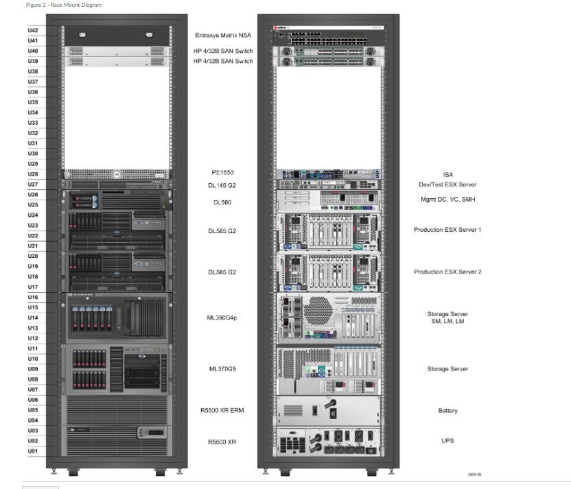
Deliverables: You have two deliverables. The first is the detailed logical network diagram following the instructions above. The second is a detailed rack mount diagram for your core network domain, edge network domain, and DMZ equipment. See Figure 2 for an example.
Figure 1 - Example Logical Diagram
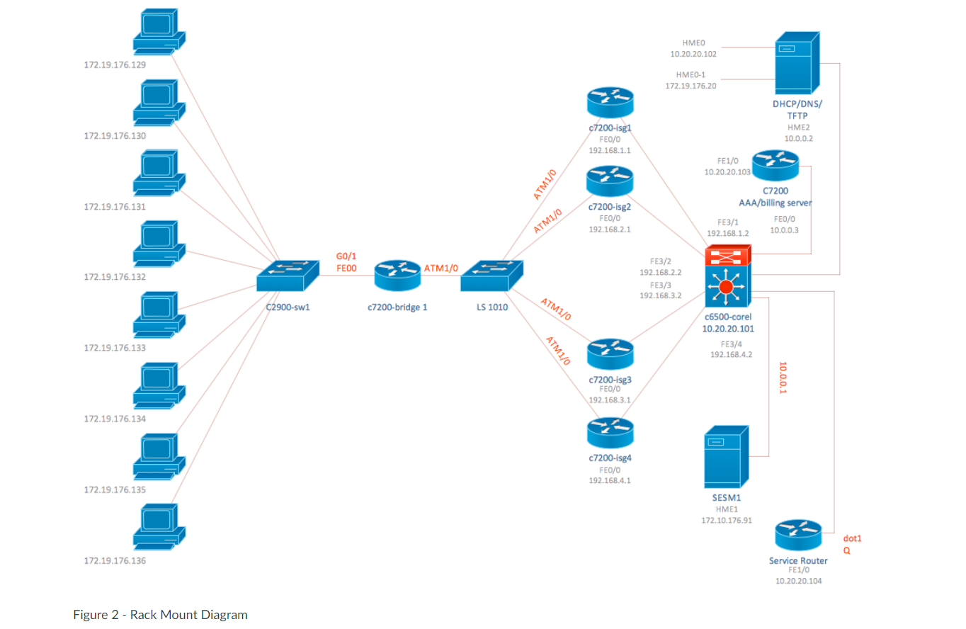
HMEO 10.20.20.102 172.19.176.129 HME0-1 172.19.176.20 DHCP/DNS/ TFTP HME2 10.0.0.2 172.19.176.130 c7200-isg1 FE0/0 192.168.1.1 FE1/0 10.20.20.103 ATM1/0 172.19.176.131 c7200-isg2 FE0/0 192.168.2.1 C7200 AAA/billing server FE0/0 FE3/1 192.168.1.2 10.0.0.3 ATM1/0 / G0/1 FEDO ATM1/0 172.19.176.132 FE3/2 192.168.2.2 FE3/3 192.168.3.2 C2900-swi ATM1/0 c7200-bridge 1 LS 1010 c6500-corel 10.20.20.101 FE3/4 192.168.4.2 172.19.176.133 ATM1/0 c7200-isg3 FE0/0 192.168.3.1 10.0.0.1 172.19.176.134 c7200-isg4 FE0/0 192.168.4.1 172.19.176.135 SESM1 HME1 172.10.176.91 doti Q 172.19.176.136 Service Router FE1/0 10.20.20.104 Figure 2 - Rack Mount Diagram Figure 2 - Rack Mount Diagram U42 141 140 U39 Entrasys Matrix NSA HP 4/32B SAN Switch HP 4/32B SAN Swich US U37 U36 U35 U34 U33 U32 U31 U30 29 128 U27 U26 u2s PE 1550 DL 145 G2 ISA Dev/Test ESX Server DL560 Mgmt DC, VC, SMH 124 DL586 G2 U23 U22 U21 Production ESX Server 1 U20 U19 U18 DL585 G2 Production ESX Server 2 U17 DODGDL ML 350G4p U16 U15 U14 U13 U12 U11 U10 U09 Storage Server SM, LM, LM FELDEN ML370G5 Storage Server U08 UO7 006 105 R5500 XR ERM Battery 104 103 UO2 101 R5600 XR UPS HMEO 10.20.20.102 172.19.176.129 HME0-1 172.19.176.20 DHCP/DNS/ TFTP HME2 10.0.0.2 172.19.176.130 c7200-isg1 FE0/0 192.168.1.1 FE1/0 10.20.20.103 ATM1/0 172.19.176.131 c7200-isg2 FE0/0 192.168.2.1 C7200 AAA/billing server FE0/0 FE3/1 192.168.1.2 10.0.0.3 ATM1/0 / G0/1 FEDO ATM1/0 172.19.176.132 FE3/2 192.168.2.2 FE3/3 192.168.3.2 C2900-swi ATM1/0 c7200-bridge 1 LS 1010 c6500-corel 10.20.20.101 FE3/4 192.168.4.2 172.19.176.133 ATM1/0 c7200-isg3 FE0/0 192.168.3.1 10.0.0.1 172.19.176.134 c7200-isg4 FE0/0 192.168.4.1 172.19.176.135 SESM1 HME1 172.10.176.91 doti Q 172.19.176.136 Service Router FE1/0 10.20.20.104 Figure 2 - Rack Mount Diagram Figure 2 - Rack Mount Diagram U42 141 140 U39 Entrasys Matrix NSA HP 4/32B SAN Switch HP 4/32B SAN Swich US U37 U36 U35 U34 U33 U32 U31 U30 29 128 U27 U26 u2s PE 1550 DL 145 G2 ISA Dev/Test ESX Server DL560 Mgmt DC, VC, SMH 124 DL586 G2 U23 U22 U21 Production ESX Server 1 U20 U19 U18 DL585 G2 Production ESX Server 2 U17 DODGDL ML 350G4p U16 U15 U14 U13 U12 U11 U10 U09 Storage Server SM, LM, LM FELDEN ML370G5 Storage Server U08 UO7 006 105 R5500 XR ERM Battery 104 103 UO2 101 R5600 XR UPS
Step by Step Solution
There are 3 Steps involved in it

Get step-by-step solutions from verified subject matter experts