

Question: Please help this is PROCESS CONTROL. PROCESS CONTROL THANKS. 1.3. Two flow control loops are shown in Figure 1. Indicate whether each system is either
Please help this is PROCESS CONTROL.
PROCESS CONTROL THANKS.
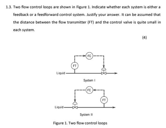
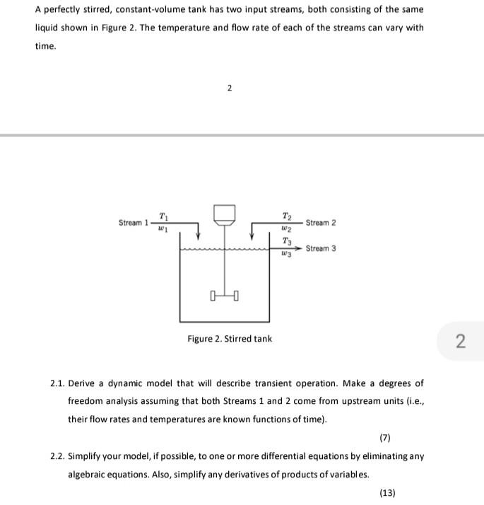
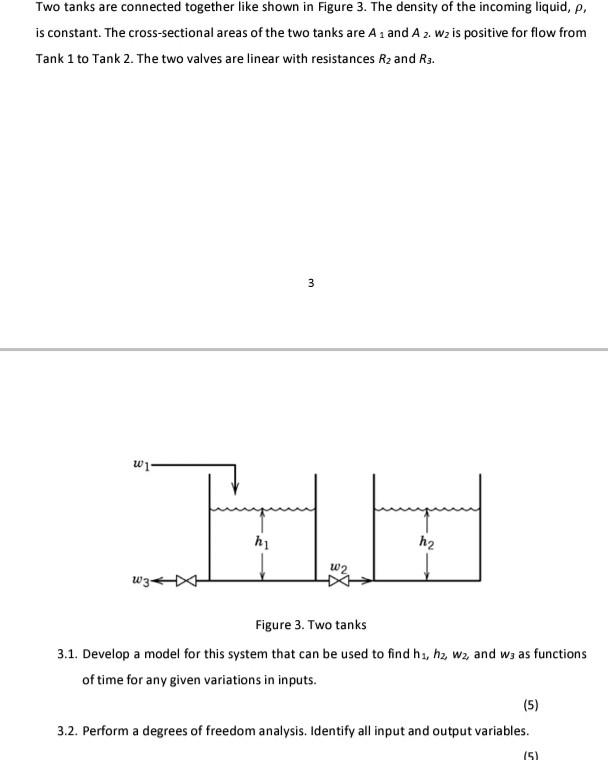
1.3. Two flow control loops are shown in Figure 1. Indicate whether each system is either a feedback or a feedforward control system. Justify your answer. It can be assumed that the distance between the flow transmitter (FT) and the control valve is quite small in each system. (4) 4) FC Liquid System FC Liquid- System 11 Figure 1. Two flow control loops A perfectly stirred, constant-volume tank has two input streams, both consisting of the same liquid shown in Figure 2. The temperature and flow rate of each of the streams can vary with time. Stream 1 71 W1 T2 w2 Stream 2 Stream 3 TIF Figure 2. Stirred tank 2 2.1. Derive a dynamic model that will describe transient operation. Make a degrees of freedom analysis assuming that both Streams 1 and 2 come from upstream units (i.e., their flow rates and temperatures are known functions of time). (7) 2.2. Simplify your model, if possible, to one or more differential equations by eliminating any algebraic equations. Also, simplify any derivatives of products of variables. (13) Two tanks are connected together like shown in Figure 3. The density of the incoming liquid, p. is constant. The cross-sectional areas of the two tanks are A and A 2. Wz is positive for flow from Tank 1 to Tank 2. The two valves are linear with resistances Rz and R3. m w 3 w1 TH L pro h2 w2 W3- Figure 3. Two tanks 3.1. Develop a model for this system that can be used to find h, h2, W2, and ws as functions of time for any given variations in inputs. (5) 3.2. Perform a degrees of freedom analysis. Identify all input and output variables. 151
Step by Step Solution
There are 3 Steps involved in it

Get step-by-step solutions from verified subject matter experts