

Question: The circuit of Figure 5.5 on the facing page demonstrates how an induc- tor can produce a high-voltage pulse across a load resistance Rload
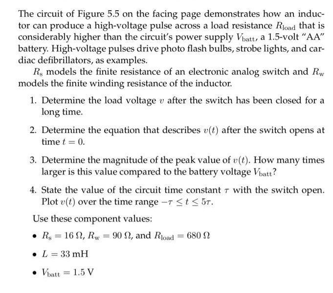
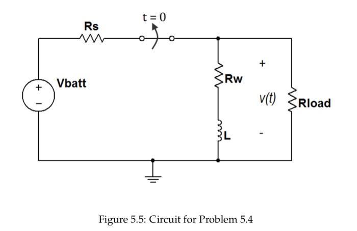
The circuit of Figure 5.5 on the facing page demonstrates how an induc- tor can produce a high-voltage pulse across a load resistance Rload that is considerably higher than the circuit's power supply Vbatt, a 1.5-volt "AA" battery. High-voltage pulses drive photo flash bulbs, strobe lights, and car- diac defibrillators, as examples. R, models the finite resistance of an electronic analog switch and Rw models the finite winding resistance of the inductor. 1. Determine the load voltage v after the switch has been closed for a long time. 2. Determine the equation that describes v(t) after the switch opens at time t = 0. 3. Determine the magnitude of the peak value of v(t). How many times larger is this value compared to the battery voltage Vbatt? 4. State the value of the circuit time constant 7 with the switch open. Plot v(t) over the time range - t 5t. Use these component values: Rs 16, Rw = 90 , and Road . L = 33 mH Vbatt = 1.5 V = = 680 + Rs Vbatt t = 0 g ww www Rw Figure 5.5: Circuit for Problem 5.4 v(t) Rload
Step by Step Solution
3.43 Rating (150 Votes )
There are 3 Steps involved in it

Get step-by-step solutions from verified subject matter experts