

Question: ****** Please it has to be solved by MATLAB ****** Explanation: The voltage-versus-current characteristic of a practical diode at forward biased region (v D >
****** Please it has to be solved by MATLAB ******
Explanation: The voltage-versus-current characteristic of a practical diode at forward biased region (vD > 0) can be approximated by the Shockley diode equation:
iD = IS(e(vD/(nVT)) - 1), (1)
where
- iD is the current [A] through the diode,
- vD is the diode voltage [V],
- IS is the leakage (or reverse saturation) current, typically in the range of 10-6 A to 10-15 A,
- n is the empirical constant known as the emission coefficient or the ideality factor, whose value varies from 1 to 2,
- VT is a constant called the thermal voltage.
The diode current iD will be very small if the diode voltage vD is less than a specific value VTD, known as the threshold voltage or the cut-in voltage or the turn-on voltage (typically 0.7 = V). The diode conducts fully if vD is higher than VTD. Thus, the threshold voltage is the voltage at which a forward-biased diode begins to conduct fully. For vD > 0.1 V, which is usually the case, iD >> IS, and Eq. (1) can be approximated by
iD = IS (e(vD/(nVT)) - 1) IS e(vD/(nVT)) . (2)
Question: The voltage-versus-current characteristic of a diode at forward biased region (vD > 0) is measured at a junction temperature of 25 C and the measured values are plotted in Figure 1 and given in the data file (fprdata.dat), where the first column is the voltage in V and the second column is the measured current in A. This diode is used in the RL circuit shown in Figure 2, where the switch is closed at t = t0. Formulate and write a code to calculate the current i(t), voltages v1(t), v2(t), and vD(t) for VS = 2 V, L=0.98 H, R = 14.2 , t0 = 0 s, and i0 = 0 A for the time interval t [0.600] ms using the step sizes t = 25 ms and t = 2.5 ms. Assume that vD(0) = 0 V for t = 0 s.
Followings should be included:
- Formulation for the initial value problem.
- Formulation of the method used to handle the diode characteristic.
- Plots of the current i(t), voltages v1(t), v2(t), and vD(t) versus time t.
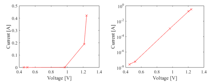
Figure 1: The measured voltage-current characteristic of a diode at forward biased region: (a) linear, (b) logarithmic scales.
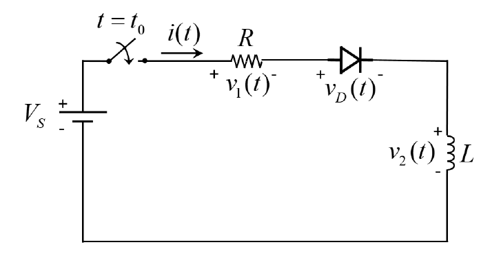
Figure 2: Circuit for the final project.
- Which methods are used? Explain why they are chosen.
- Include all necessary values and figures (depending on the used methods).
*************** fprdata.dat *************
+4.60000E-01 +2.39944E-08
+5.00000E-01 +5.47030E-08
+9.70000E-01 +1.15987E-03
+1.21200E+00 +1.90309E-01
+1.24300E+00 +4.21568E-01
***************************************
0.5 10 0.4 102 203) Current [A] Current [A] 10+ 0.2 10-6 0.1 0 0.4 10-8 0.6 1.2 1.4 0.4 0.6 1.2 1.4 0.8 Voltage [V] 0.8 1 Voltage [V] t=ts (1) X, R + + (1) + V S (1) 3L 0.5 10 0.4 102 203) Current [A] Current [A] 10+ 0.2 10-6 0.1 0 0.4 10-8 0.6 1.2 1.4 0.4 0.6 1.2 1.4 0.8 Voltage [V] 0.8 1 Voltage [V] t=ts (1) X, R + + (1) + V S (1) 3L
Step by Step Solution
There are 3 Steps involved in it

Get step-by-step solutions from verified subject matter experts