

Question: Please layout the multiplexer condition table for the given ASM chart below... Thanks! TO T1 01 T3 T2 10 ASM chart 2 the control logic
Please layout the multiplexer condition table for the given ASM chart below...
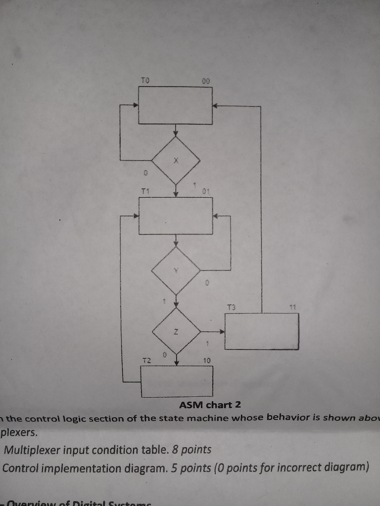
Thanks!
TO T1 01 T3 T2 10 ASM chart 2 the control logic section of the state machine whose behavior is shown abo plexers Multiplexer input condition table. 8 points Control implementation diagram. 5 points (0 points for incorrect diagram)
Step by Step Solution
There are 3 Steps involved in it
1 Expert Approved Answer
Step: 1 Unlock

Question Has Been Solved by an Expert!
Get step-by-step solutions from verified subject matter experts
Step: 2 Unlock
Step: 3 Unlock