

Question: ( please note in the first page, motor internal gears with a 1 4 : 1 ratio! not 1 : 1 4 ! ) In
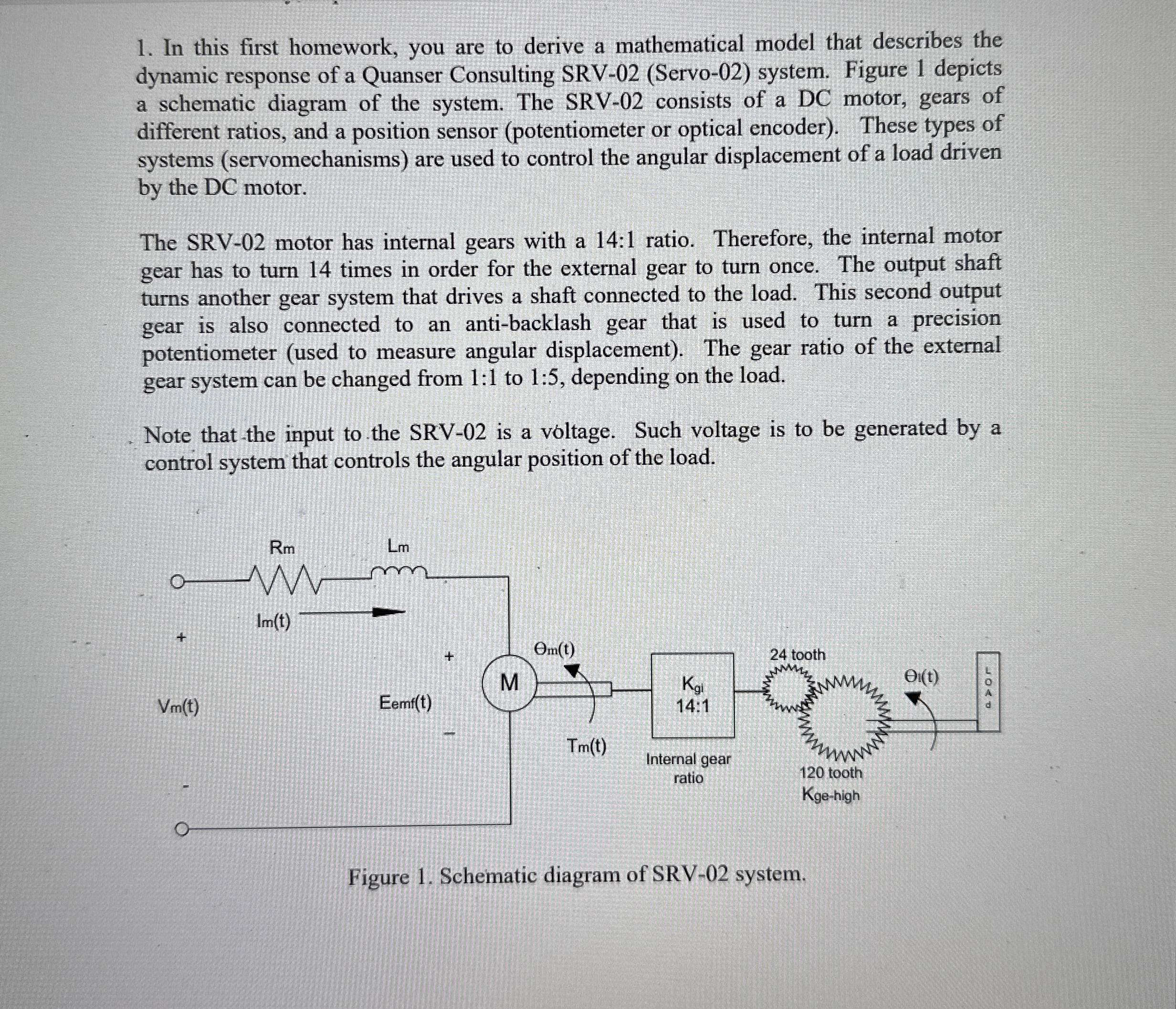
please note in the first page, motor internal gears with a : ratio! not : In this first homework, you are to derive a mathematical model that describes the dynamic response of a Quanser Consulting SRVServo system. Figure depicts a schematic diagram of the system. The SRV consists of a DC motor, gears of different ratios, and a position sensor potentiometer or optical encoder These types of systems servomechanisms are used to control the angular displacement of a load driven by the DC motor. Table System's electrical and mechanical parameters.
tableSymbolName,Value,UnitsKtMotor Torque Constant,NmAmpsKmBack EMF Constant,VradsRmArmature Resistance,Omega KgiGearbox Ratio Internal:NAKgehigh External High Gear Ratio,:NAKgelow External Low Gear Ratio,:NAJmMotor Inertia,ekgmJtach Tachometer Inertia,ekgmJeqlow,Equivalent Low Gear Inertia,ekgmJeqhigh Equivalent High Gear Inertia, ekgmJarmatend Armatend inertia,KgmJge tooth, tooth gear inertia, eKgmJarmatcenter,Armatcenter inertia, eKgmLmArmature inductance,mHJge tooth, tooth gear inertia, eKgmJge tooth, tooth gear inertia,,KgmBeqhigh tableViscous Damping CoefficientHigheNmradsBeqlow tableViscous Damping CoefficientLoweNmradsKtach Tachometer Sensitivity,VRPMEff m Motor Efficiency,NAEffGearbox Efficiency,NA The plant's transfer function is of the following form,
olts
where is the angular displacement of the load, is the voltage applied to the motor,
is the plant's constant and is the negative of the plant's pole.
a Write a set of differential and algebraic equations that are necessary and sufficient to
describe the dynamic response of the SRV system. Use the parameters and their
respective symbols shown in Table
b Use the results obtained in part to determine the transfer function of the system.
c Explain the assumptions that were necessary to obtain the type of transfer function
specified in the problem,
olts
and determine the expressions for and in terms of the other system parameters.
The SRV motor has internal gears with a : ratio. Therefore, the internal motor gear has to turn times in order for the external gear to turn once. The output shaft turns another gear system that drives a shaft connected to the load. This second output gear is also connected to an antibacklash gear that is used to turn a precision potentiometer used to measure angular displacement The gear ratio of the external gear system can be changed from : to : depending on the load.
Note that the input to the SRV is a voltage. Such voltage is to be generated by a control system that controls the angular position of the load.
Step by Step Solution
There are 3 Steps involved in it
1 Expert Approved Answer
Step: 1 Unlock

Question Has Been Solved by an Expert!
Get step-by-step solutions from verified subject matter experts
Step: 2 Unlock
Step: 3 Unlock