

Question: Please read this carefully. A skeleton was provided. Program must be in C. [20] 5) Write a C program using the MSP430G2553 Launchpad which creates
Please read this carefully. A skeleton was provided. Program must be in C.
![C. [20] 5) Write a C program using the MSP430G2553 Launchpad which](https://dsd5zvtm8ll6.cloudfront.net/si.experts.images/questions/2024/09/66f4e2f02b66c_91166f4e2ef961d8.jpg)
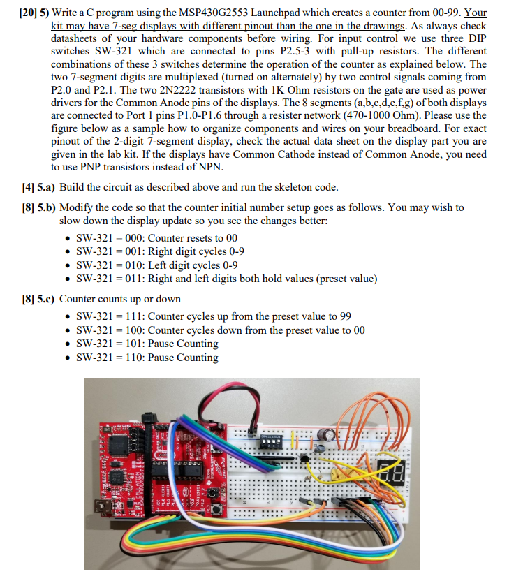
[20] 5) Write a C program using the MSP430G2553 Launchpad which creates a counter from 00-99. Your kit may have 7-seg displays with different pinout than the one in the drawings. As always check datasheets of your hardware components before wiring. For input control we use three DIP switches SW-321 which are connected to pins P2.5-3 with pull-up resistors. The different combinations of these 3 switches determine the operation of the counter as explained below. The two 7-segment digits are multiplexed (turned on alternately) by two control signals coming from P2.0 and P2.1. The two 2N2222 transistors with 1K Ohm resistors on the gate are used as power drivers for the Common Anode pins of the displays. The 8 segments (a,b.c,d,e,f,g) of both displays are connected to Port 1 pins P1.0-P1.6 through a resister network (470-1000 Ohm). Please use the figure below as a sample how to organize components and wires on your breadboard. For exact pinout of the 2-digit 7-segment display, check the actual data sheet on the display part you are given in the lab kit. If the displays have Common Cathode instead of Common Anode. you need to use PNP transistors instead of NPN [4] 5.a) Build the circuit as described above and run the skeleton code [8] 5.b) Modify the code so that the counter initial number setup goes as follows. You may wish to slow down the display update so you see the changes better: SW-321 000: Counter resets to 00 . SW-321-001: Right digit cycles 0-9 * SW-321 010: Left digit cycles 0-9 * SW-321- 011: Right and left digits both hold values (preset value) [8] 5.c) Counter counts up or down . SW-321-11: Counter cycles up from the preset value to 99 SW-321-100: Counter cycles down from the preset value to 00 . SW-321- 101: Pause Counting . SW-321- 110: Pause Counting [20] 5) Write a C program using the MSP430G2553 Launchpad which creates a counter from 00-99. Your kit may have 7-seg displays with different pinout than the one in the drawings. As always check datasheets of your hardware components before wiring. For input control we use three DIP switches SW-321 which are connected to pins P2.5-3 with pull-up resistors. The different combinations of these 3 switches determine the operation of the counter as explained below. The two 7-segment digits are multiplexed (turned on alternately) by two control signals coming from P2.0 and P2.1. The two 2N2222 transistors with 1K Ohm resistors on the gate are used as power drivers for the Common Anode pins of the displays. The 8 segments (a,b.c,d,e,f,g) of both displays are connected to Port 1 pins P1.0-P1.6 through a resister network (470-1000 Ohm). Please use the figure below as a sample how to organize components and wires on your breadboard. For exact pinout of the 2-digit 7-segment display, check the actual data sheet on the display part you are given in the lab kit. If the displays have Common Cathode instead of Common Anode. you need to use PNP transistors instead of NPN [4] 5.a) Build the circuit as described above and run the skeleton code [8] 5.b) Modify the code so that the counter initial number setup goes as follows. You may wish to slow down the display update so you see the changes better: SW-321 000: Counter resets to 00 . SW-321-001: Right digit cycles 0-9 * SW-321 010: Left digit cycles 0-9 * SW-321- 011: Right and left digits both hold values (preset value) [8] 5.c) Counter counts up or down . SW-321-11: Counter cycles up from the preset value to 99 SW-321-100: Counter cycles down from the preset value to 00 . SW-321- 101: Pause Counting . SW-321- 110: Pause Counting
Step by Step Solution
There are 3 Steps involved in it

Get step-by-step solutions from verified subject matter experts