

Question: please see attached Please present the tables below For road: In the table, '+' is cut, and '-' is fill Depth matrix A B C
please see attached
Please present the tables below
For road:In the table, '+' is cut, and '-' is fill
| Depth matrix | A | B | C | D | E | F | G | H |
| 1 | ||||||||
| 2 | ||||||||
| Depth matrix | I | J | K | L | M | N | O | P |
| 1 | ||||||||
| 2 |
For building pad:In the table, '+' is cut, and '-' is fill
| Depth matrix | a | b | c | d |
| 1 | ||||
| 2 | ||||
| 3 |
2.2 Please demonstrate the calculation steps for each grid by grid method, average end area method, or prismoidal method.
2.3 Please fill out the table below to indicate the cut and fill schedules.
| Topography - Road | Cut | Fill | Net cut/fill |
| Topography - Building | Cut | Fill | Net cut/fill |
| Topography - Total | Cut | Fill | Net cut/fill |
2.4 Please present the screenshot of your measurement for Part 2 Road pavement, if you use software (i.e. CostX) to do so.
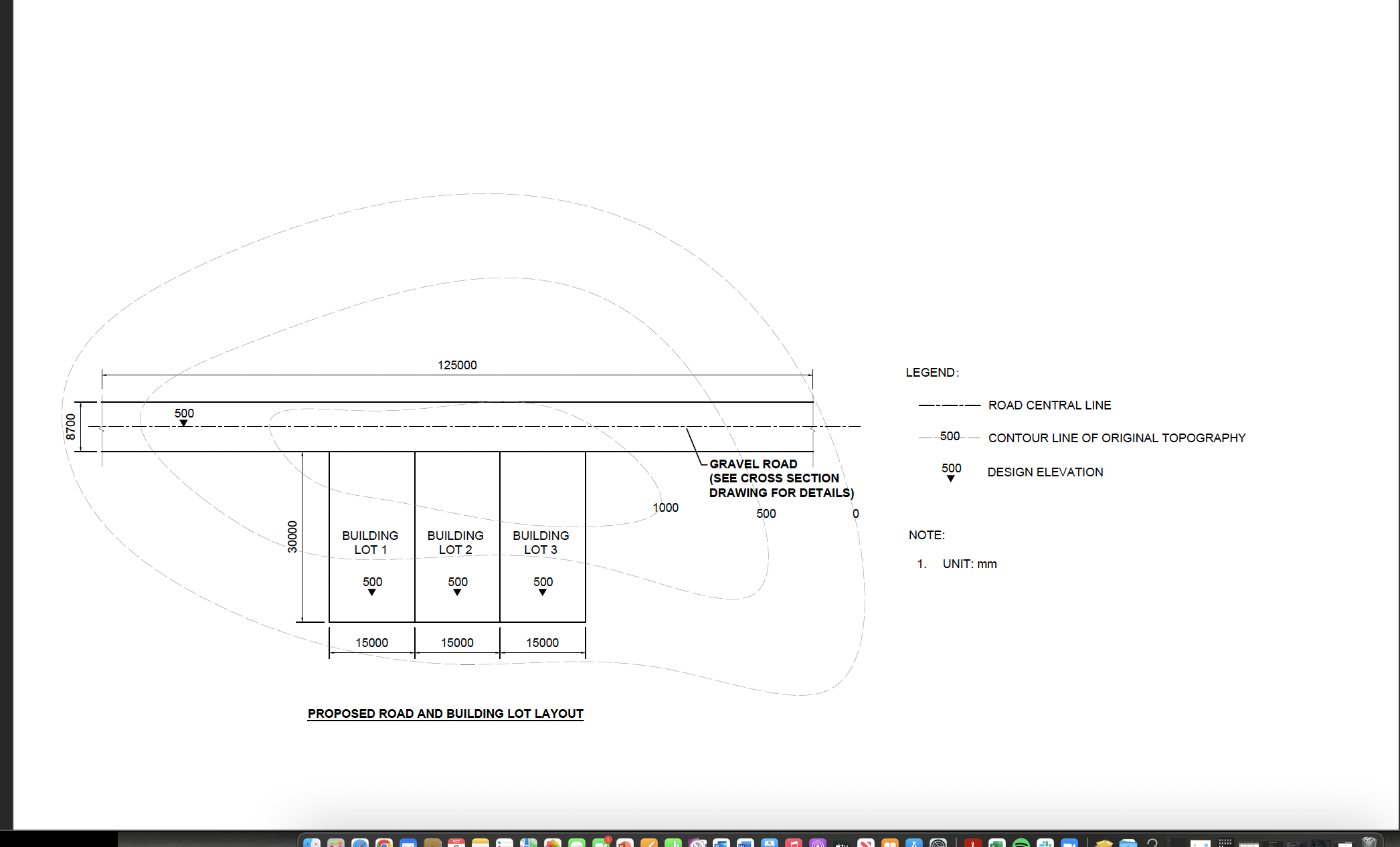
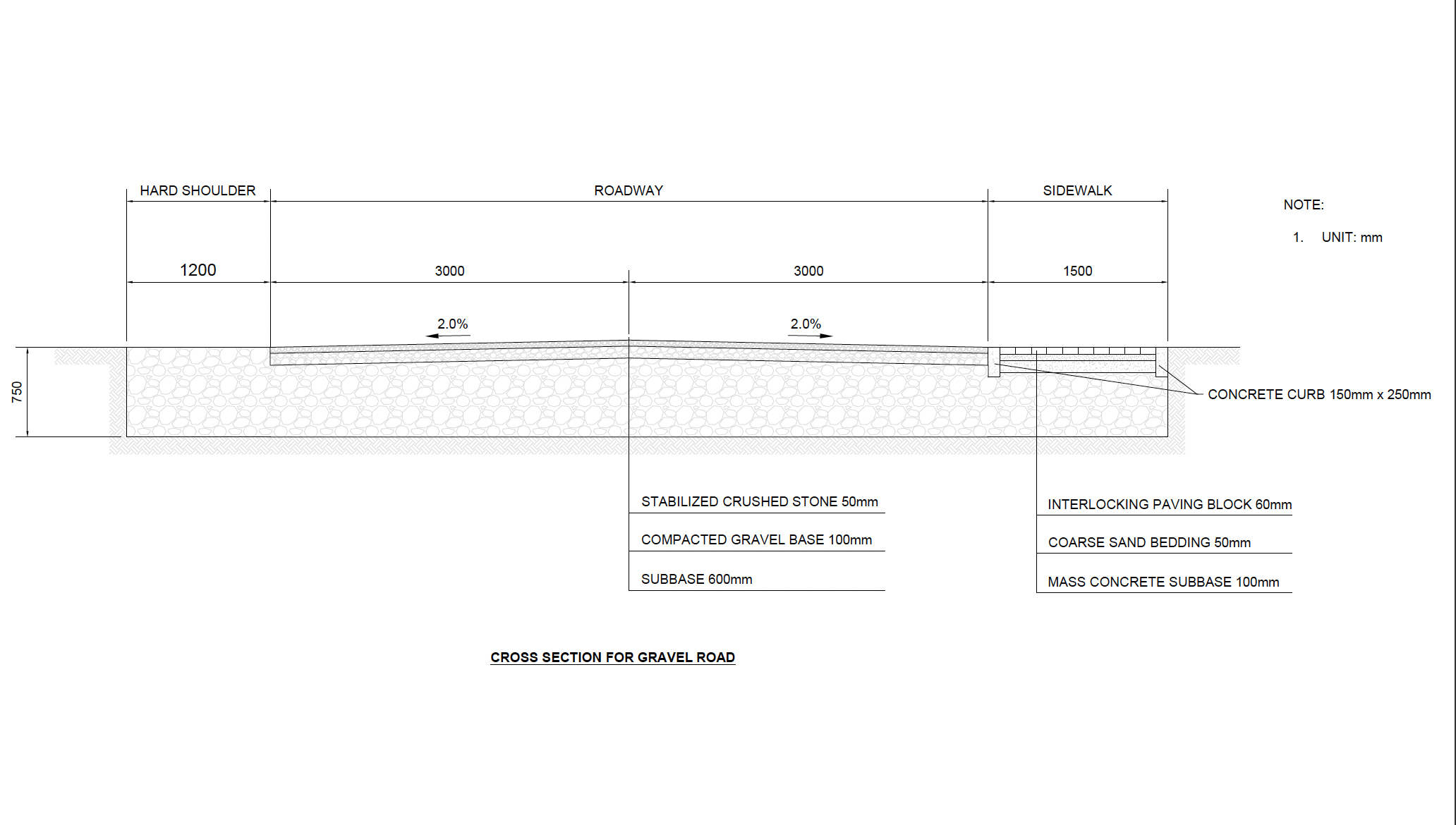
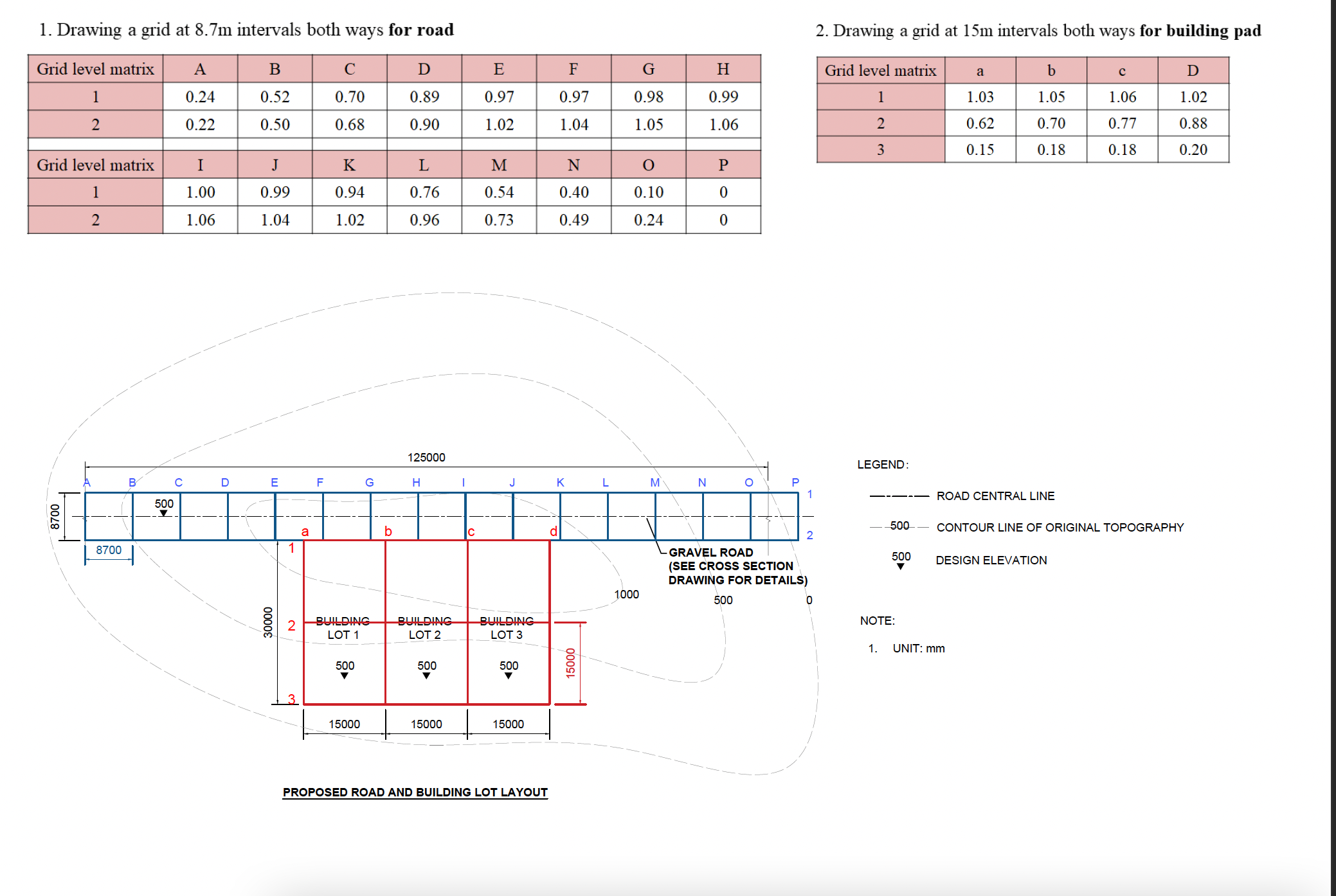
125000 LEGEND: ROAD CENTRAL LINE 500 8700 500 CONTOUR LINE OF ORIGINAL TOPOGRAPHY GRAVEL ROAD 500 (SEE CROSS SECTION DESIGN ELEVATION DRAWING FOR DETAILS) 1000 500 NOTE: 30000 BUILDING BUILDING BUILDING LOT 1 LOT 2 LOT 3 1. UNIT: mm 500 500 500 15000 15000 15000 PROPOSED ROAD AND BUILDING LOT LAYOUTHARD SHOULDER ROAD WAY SIDEWALK 1200 3000 3000 NOTE: 1. UNIT: mm 1500 750 T k CONCRETE CURB 150mm x 250mm SUBBASE 600mm CROSS SECTION FOR GRAVEL ROAD STABILIZED CRUSHED STONE 50mm COMPACTED GRAVEL BASE 100mm INTERLOCKING PAVING BLOCK 60mm COARSE SAND BEDDING 50mm MASS CONCRETE SUBBASE 100mm 1. Drawing a grid at 8.7m intervals both ways for road 2. Drawing a grid at 15m intervals both ways for building pad Grid level matrix A B C D E F G H Grid level matrix a b C D 0.24 0.52 0.70 0.89 0.97 0.97 0.98 0.99 1.03 1.05 1.06 1.02 2 0.22 0.50 0.68 0.90 1.02 1.04 1.05 1.06 2 0.62 0.70 0.77 0.88 Grid level matrix 3 K L M N 0.15 O 0.18 0.18 P 0.20 1.00 0.90 0.94 0.7 0.54 0.4 0.10 0 2 1.06 1.04 1.02 0.96 0.73 0.49 0.24 0 125000 B LEGEND: C D E F G H J K L M N O 500 - ROAD CENTRAL LINE 8700 b 500 CONTOUR LINE OF ORIGINAL TOPOGRAPHY 8/00 GRAVEL ROAD 500 SEE CROSS SECTION DESIGN ELEVATION DRAWING FOR DETAILS) 1000 500 30000 BUILDING BUILDING BUILDING N LOT 1 NOTE: LOT 2 LOT 3 1. UNIT: mm 500 500 500 1500 2 15000 15000 15000 PROPOSED ROAD AND BUILDING LOT LAYOUT
Step by Step Solution
There are 3 Steps involved in it

Get step-by-step solutions from verified subject matter experts