

Question: Please show all steps, I will give thumbs up/ Upvote immediately if solved fully complete Refer to the sketch below. Complete the given table by
Please show all steps, I will give thumbs up/ Upvote immediately if solved fully complete
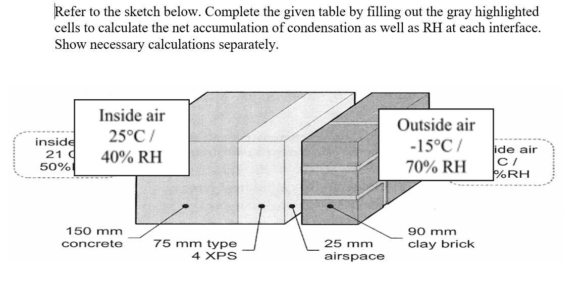
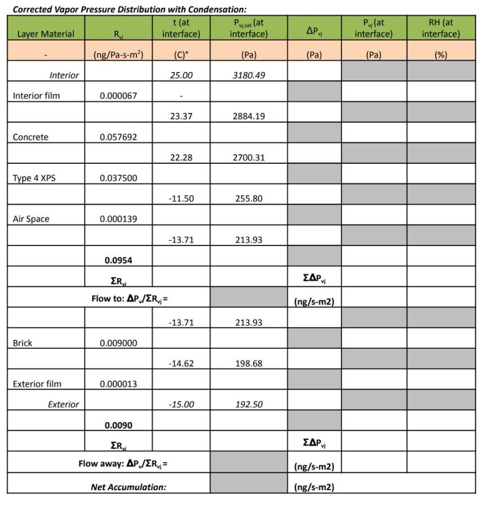
Refer to the sketch below. Complete the given table by filling out the gray highlighted cells to calculate the net accumulation of condensation as well as RH at each interface. Show necessary calculations separately. inside 21 g 50%! Inside air 25C/ 40% RH Outside air -15C/ 70% RH ide air C/ %RH 90 mm 150 mm concrete 75 mm type 4 XPS 25 mm airspace clay brick Corrected Vapor Pressure Distribution with Condensation: t (at Pui.sat (at Layer Material RE interface) interface) , Pv Pulat interface) RH (at interface) (ng/Pa-s-m) (C) (Pa) (Pa) (Pa) ( %) Interior 25.00 3180.49 Interior film 0.000067 23.37 2884.19 Concrete 0.057692 22.28 2700.31 Type 4 XPS 0.037500 -11.50 255.80 Air Space 0.000139 -13.71 213.93 0.0954 EAP vi ERvi Flow to: AP /ER;= (ng/s-m2) -13.71 213.93 Brick 0.009000 -14.62 198.68 Exterior film 0.000013 Exterior -15.00 192.50 0.0090 ER EAP vi Flow away: AP/ER; = (ng/s-m2) Net Accumulation: (ng/s-m2)
Step by Step Solution
There are 3 Steps involved in it

Get step-by-step solutions from verified subject matter experts