

Question: 1. (a) Draw the equivalent circuit and vector diagram of nominal T method of medium transmission [1] line. (b) Determine the generalized circuit constants
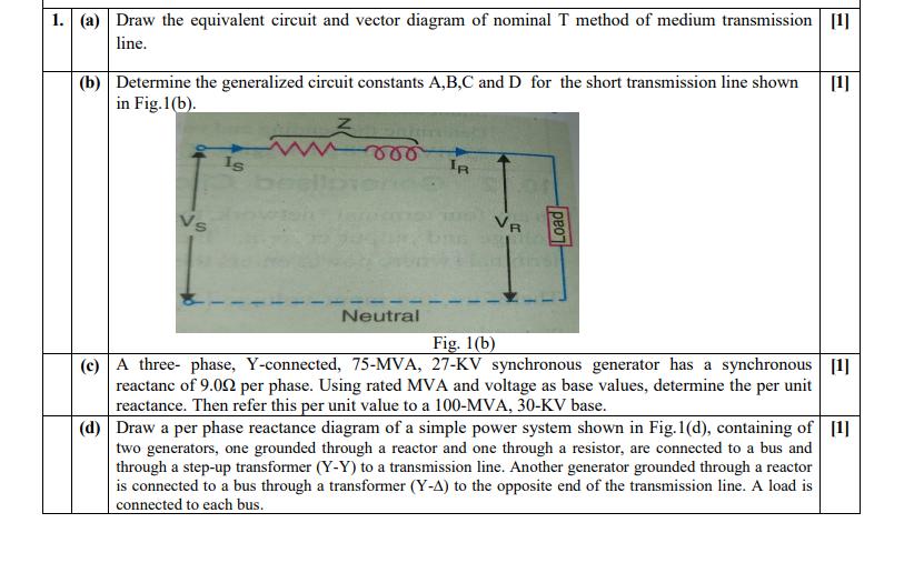
1. (a) Draw the equivalent circuit and vector diagram of nominal T method of medium transmission [1] line. (b) Determine the generalized circuit constants A,B,C and D for the short transmission line shown [1] in Fig.1(b). Is be wroo m Neutral IR VR Load Fig. 1(b) (c) A three-phase, Y-connected, 75-MVA, 27-KV synchronous generator has a synchronous [1] reactanc of 9.00 per phase. Using rated MVA and voltage as base values, determine the per unit reactance. Then refer this per unit value to a 100-MVA, 30-KV base. (d) Draw a per phase reactance diagram of a simple power system shown in Fig.1(d), containing of [1] two generators, one grounded through a reactor and one through a resistor, are connected to a bus and through a step-up transformer (Y-Y) to a transmission line. Another generator grounded through a reactor is connected to a bus through a transformer (Y-A) to the opposite end of the transmission line. A load is connected to each bus.
Step by Step Solution
3.40 Rating (156 Votes )
There are 3 Steps involved in it
C Given foom MVA Impedance Dutigran z base X formula Reactance Diagram To find 1 ZpU In 2pu Zbase no... View full answer

Get step-by-step solutions from verified subject matter experts