

Question: Please solve for V - I time difference, Phase shift, and Resistor current in the below table Use Multisim to perform an AC sweep of
Please solve for VI time difference, Phase shift, and Resistor current in the below table Use Multisim to perform an AC sweep of this circuit, and plot both voltage and phase. This is a "Bode Plot" see your textbook. Do this by placing a Measurement Probe between the capacitor and the resistor ie the output and run an AC Analysis..." from the Simulation menu. Set the frequency limits from Hz to kHz specify Output to measure the voltage of the probe, and click "Simulate". Make sure to include this in your report. Comment on the shape of the curves:
Question: Would this be a highpass filter or a lowpass filter?
Question: At approximately which frequency would be the halfpower point?
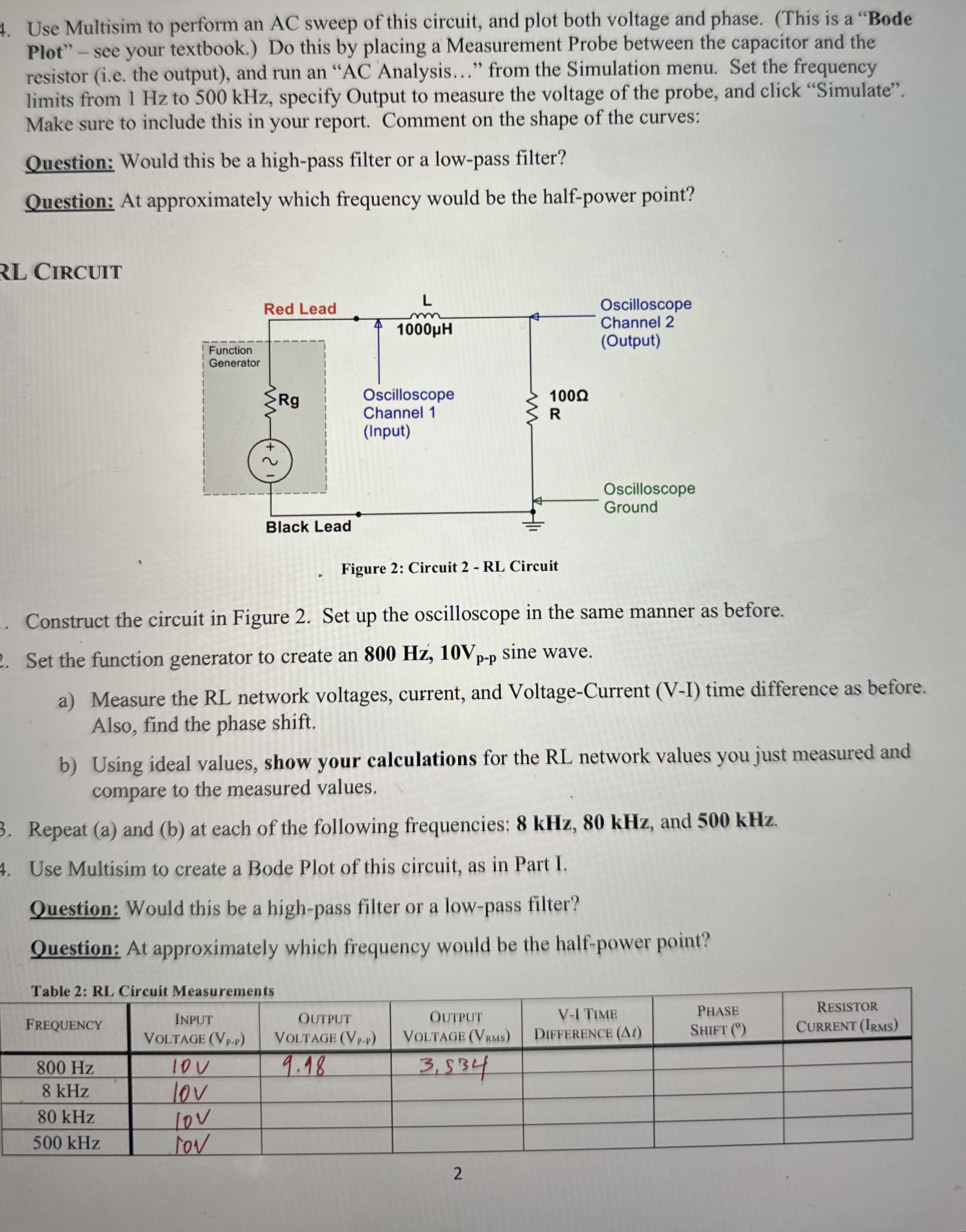
RL Circuit
Figure : Circuit RL Circuit
Construct the circuit in Figure Set up the oscilloscope in the same manner as before.
Set the function generator to create an sine wave.
a Measure the RL network voltages, current, and VoltageCurrent VI time difference as before. Also, find the phase shift.
b Using ideal values, show your calculations for the RL network values you just measured and compare to the measured values.
Repeat a and b at each of the following frequencies: and
Use Multisim to create a Bode Plot of this circuit, as in Part I.
Question: Would this be a highpass filter or a lowpass filter?
Question: At approximately which frequency would be the halfpower point?
Table : RL Circuit Measurements
tableFrequency Input
Voltage tableOutput
Step by Step Solution
There are 3 Steps involved in it
1 Expert Approved Answer
Step: 1 Unlock

Question Has Been Solved by an Expert!
Get step-by-step solutions from verified subject matter experts
Step: 2 Unlock
Step: 3 Unlock