

Question: use HDLBits simulator to answer the question. Code for part A: module top_module ();reg clk=0;always #5 clk = ~clk; // Create clock with period=10initial `probe_start;
use HDLBits simulator to answer the question.
Code for part A:
module top_module ();reg clk=0;always #5 clk = ~clk; // Create clock with period=10initial `probe_start; // Start the timing diagram`probe(clk); // Probe signal "clk"// A testbenchreg x=0, y=0;wire f, g;initial begin#10 x <= 0; y <= 1;#10 x <= 1; y <= 0;#10 x <= 1; y <= 1;$display ("Hello world! The current time is (%0d ps)",$time);#50 $finish; // Quit the simulationendbug DUT ( .x(x), .y(y), .f(f), .g(g) ); // Sub-modules worktoo.endmodulemodule bug1(input x, input y, output f, output g);assign f = X ^ y; // xor operation between x and yassign g = ~x & y; // nand operation between x and y`probe(x); // Sub-modules can also have `probe()`probe(y);`probe(f);`probe(g);endmodule
Code for part B:
module top_module ();reg clk=0;always #5 clk = ~clk; // Create clock with period=10initial `probe_start; // Start the timing diagram`probe(clk); // Probe signal "clk"// A testbenchreg sel, a, b;wire m;initial begin#0 a <= 0; b <= 0; sel <= 0;#10 a <= 0; b <= 1;#10 a <= 1; b <= 0;#10 a <= 1; b <= 1;#10 a <= 0; b <= 0; sel <= 1;#10 a <= 0; b <= 1;#10 a <= 1; b <= 0;#10 a <= 1; b <= 1;$display ("Hello world! The current time is (%0d ps)",$time);#50 $finish; // Quit the simulationendP3_1b DUT ( .m(m), .sel(sel), .a(a), .b(b) ); // Sub-modules worktoo.endmodulemodule P3_1b(input a, b, sel, output m);always @(*)m = a; // m takes on the values of a by defaultif (sel=1) m = b; // unless sel=1`probe(sel);`probe(a); // Sub-modules can also have `probe()`probe(b);`probe(m);endmodule
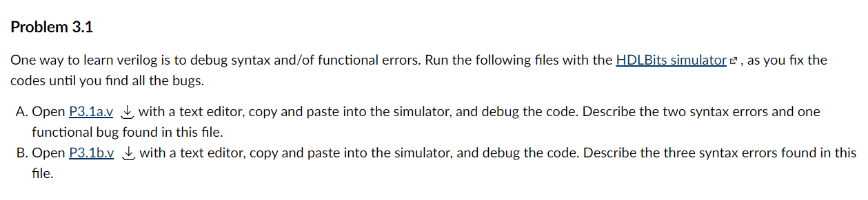
Problem 3.1 One way to learn verilog is to debug syntax and/of functional errors. Run the following files with the HDLBits simulator , as you fix the codes until you find all the bugs. A. Open P3.1a.vwith a text editor, copy and paste into the simulator, and debug the code. Describe the two syntax errors and one functional bug found in this file. B. Open P3.1b.vwith a text editor, copy and paste into the simulator, and debug the code. Describe the three syntax errors found in this file.
Step by Step Solution
3.38 Rating (148 Votes )
There are 3 Steps involved in it
Answer for Part A The code given above is for a module called topmodule which contains two submodules bug1 and DUT The bug1 module is responsible for performing the XOR and NAND operations between the inputs x and y The output of these operations is given to the DUT module which then probes the x y f and g signals The topmodule also contains a testbench which sets the initial values of x and y and then toggles them printing a message at the 10 ps mark At the 50 ps mark the simulation is ended The purpose of this code is to simulate a circuit that performs the XOR and NAND operations and probes the corresponding signals Answer for Part B The code given above is for a module called topmodule which contains one submodule ... View full answer

Get step-by-step solutions from verified subject matter experts